
Heat exchanger

a technology of heat exchanger and heat exchanger plate, which is applied in the direction of tubular elements, lighting and heating apparatus, stationary conduit assemblies, etc., can solve the problems of large installation space occupied by heat exchanger, affecting heat exchange performance, water drainage performance and appearance, etc., and achieves convenient manufacturing, reduced heat exchange efficiency, and easy bending angle

Active Publication Date: 2016-12-27
SANHUA(HANGZHOU) MICRO CHANNEL HEAT EXCHANGER CO LTD +1
View PDF20 Cites 7 Cited by
  • Summary
  • Abstract
  • Description
  • Claims
  • Application Information

AI Technical Summary

Benefits of technology

The present invention addresses problems in the prior art of heat exchangers being difficult to bend, requiring large bending radii and installation spaces, and having limited bending angles. The invention provides a heat exchanger that is easy to bend, has improved water drainage performance, and meets requirements for bending while also being long-lasting and having a good appearance. The invention takes into account the influence of bending on the tubes to ensure long service lives.

Problems solved by technology

Due to the presence of the fins at the bent position, the heat exchanger is difficult to bend during manufacturing, the bending radius must be large, the bending angle is limited, and the installation space occupied by the heat exchanger is large.
In addition, the fins at the bent position tend to be distorted, thus influencing the heat exchange performance, the water drainage performance and the appearance of the heat exchanger, and water may be blown out of or dropped into a pipe system.
However, because the segments without fins do not participate in heat exchange, if the segments without fins are too long, the effective heat exchange area may be reduced, thus affecting the heat exchange performance.
If the segments without fins are too short, the bending radius of the bent segments must be large, the bending angle is limited, and the installation space should be large, thus affecting the heat exchange performance, the water drainage performance and the appearance of the heat exchanger.
Moreover, for the conventional heat exchanger, the influence of bending upon the tubes is usually not taken into account when bending the tubes.
The larger the stretching amount of the outer surface of the bent segments of the heat exchanger, the thinner the outer wall of the tube is, therefore, the bursting strength and the corrosion resistance of the tubes are decreased, thus shortening the life of the heat exchanger.

Method used


Image

  • Heat exchanger
  • Heat exchanger
  • Heat exchanger

Examples


Embodiment Construction

[0023]Reference will be made in detail to embodiments of the present invention. The embodiments described herein with reference to the accompany drawings are explanatory and illustrative, which are used to generally understand the present invention. The embodiments shall not be construed to limit the present invention. The same or similar elements and the elements having same or similar functions are denoted by like reference numerals throughout the descriptions.

[0024]It is to be understood that phraseology and terminology used herein with reference to device or element orientation (such as, terms like “longitudinal”, “lateral”, “front”, “rear”, “right”, “left”, “lower”, “upper”, “horizontal”, “vertical”, “above”, “below”, “up”, “top”, “bottom” as well as derivative thereof such as “horizontally”, “downwardly”, “upwardly”, etc.) are only used to simplify description of the present invention, and do not alone indicate or imply that the device or element referred to must have or opera...


PUM


Abstract

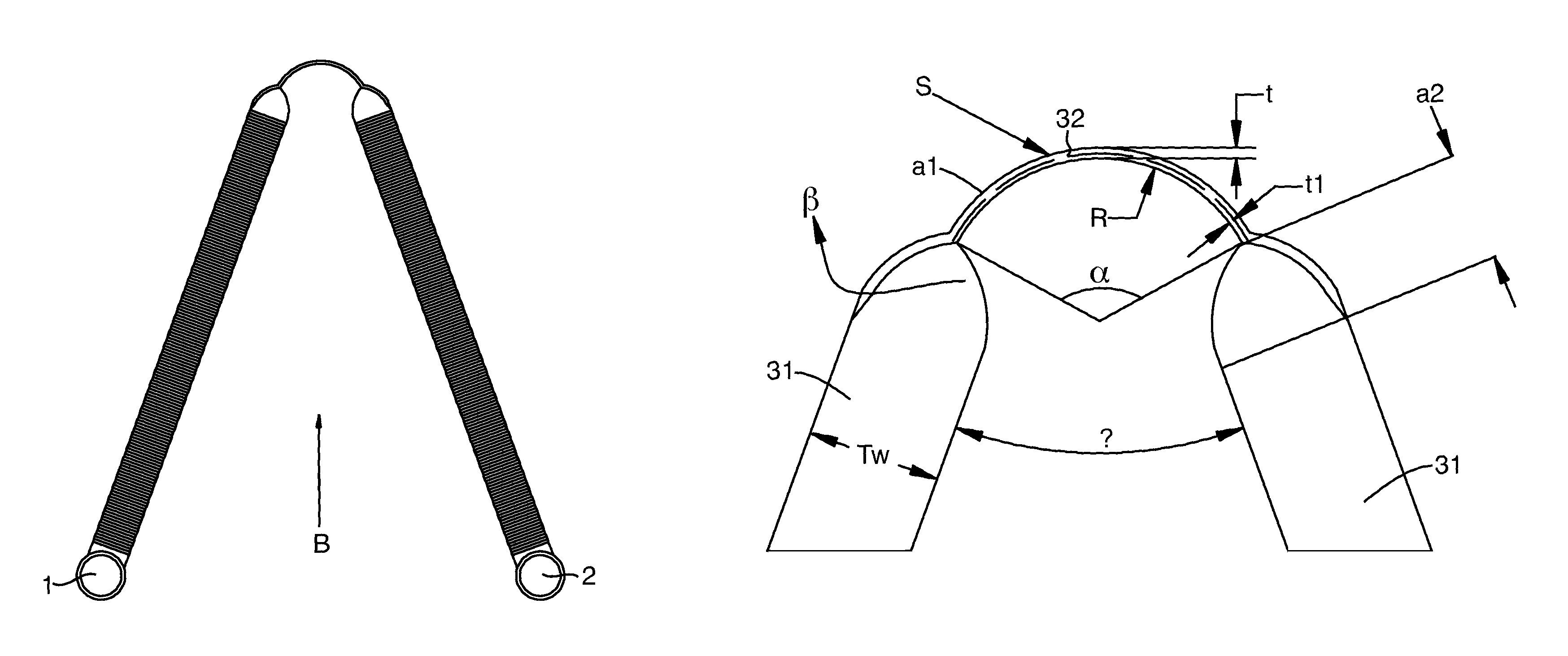
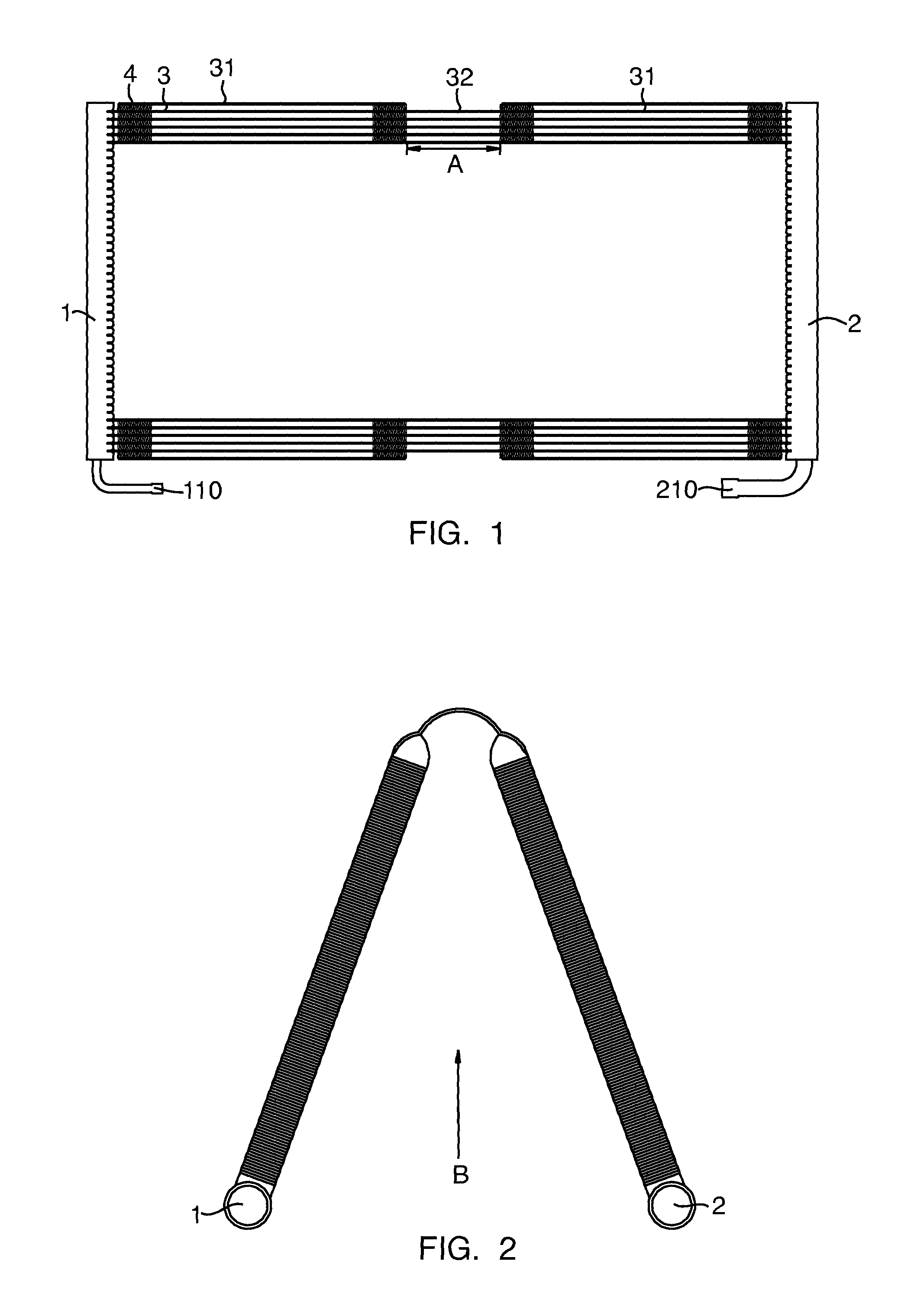
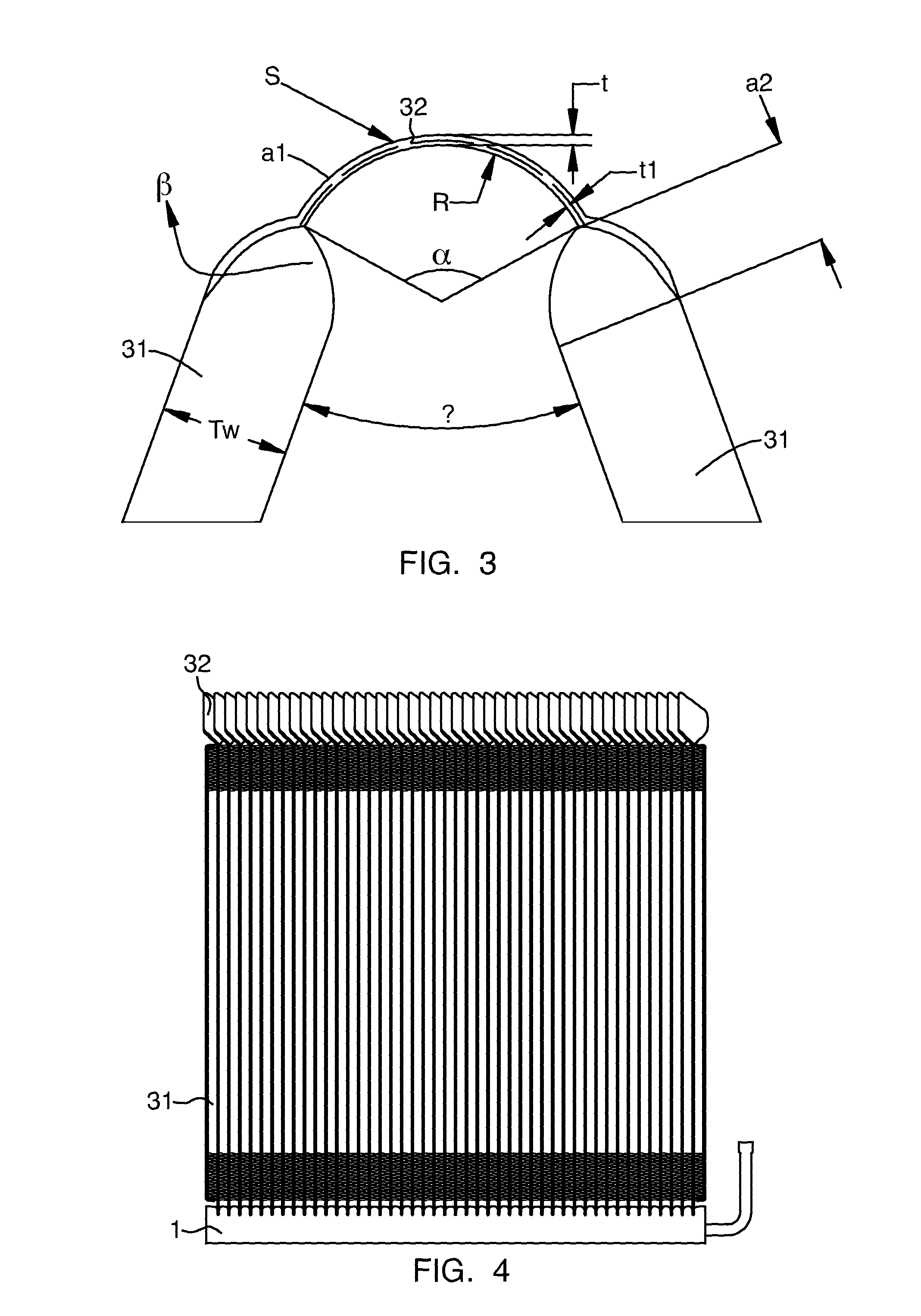
A heat exchanger includes first and second headers; a plurality of tubes each defining two ends connected to the first and second headers respectively. Each tube includes a bent segment and straight segments connected to first and second ends of the bent segment respectively, the bent segment being twisted relative to the straight segments. A plurality of fins are interposed between adjacent straight segments. A length of the bent segment before bending satisfies a formula: 5tπ(180−θ) / 180+2Tw≦A≦30tπ(180−θ) / 180+8Tw, where: A is the length of the bent segment before bending, t is a wall thickness of the tube, Tw is a width of the tube, θ is an intersection angle between the straight segments of the tube, and π is circumference ratio. The heat exchanger of embodiments of the present invention is easy to bend and convenient to manufacture without reducing the heat exchange efficiency.

Description

CROSS REFERENCE[0001]This application claims priority and benefit of Chinese Patent Application No. 201010213436.0 filed with the State Intellectual Property Office of P.R. China on Jun. 24, 2010, and Chinese Patent Application No. 201010146939.0 filed with the State Intellectual Property Office of P.R. China on Apr. 13, 2010, the contents of which are incorporated herein by reference.TECHNICAL FIELD OF THE INVENTION[0002]The present invention generally relates to a heat exchanger, more particularly, to a heat exchanger of parallel flow type.BACKGROUND OF THE INVENTION[0003]The heat exchanger is widely used in various fields. A conventional heat exchanger generally has a flat and rectangular shape of so-called parallel flow type. In order to improve the heat exchange performance to meet different requirements of application and installation, a bent heat exchanger is proposed.[0004]Due to the presence of the fins at the bent position, the heat exchanger is difficult to bend during ma...

Claims


Application Information

Patent Timeline
Patent Type & Authority Patents(United States)
IPC IPC(8): F28D7/06F28D1/053F28D1/047F28D1/00F28F9/02
CPCF28D1/047F28D1/05366F28D1/0475F28D1/0476F28F1/32
Inventor JIANG, JIANLONGWANG, WEIHUANG, LINJIE
Owner SANHUA(HANGZHOU) MICRO CHANNEL HEAT EXCHANGER CO LTD
Learn More