
Propulsion system for satellite orbit control and attitude control

a technology of satellite orbit control and attitude control, which is applied in the direction of cosmonautic vehicles, transportation and packaging, aircrafts, etc., can solve the problems of high initial mass, high cost and high mass of systems thus implemented, and disturbance of position and orientation

Active Publication Date: 2016-12-27
THALES SA
View PDF3 Cites 16 Cited by
  • Summary
  • Abstract
  • Description
  • Claims
  • Application Information

AI Technical Summary

Benefits of technology

This solution enables efficient control of satellite orbits and angular momentum, reducing the mass and cost of propulsion systems, allowing for increased payload capacity and simplified satellite architecture by controlling six orbital parameters with fewer propulsion units, thus extending satellite mission duration and reducing fuel consumption.

Problems solved by technology

In addition to the gravitational attraction of the earth, a satellite experiences several forces of lower magnitudes which progressively disturb its position and its orientation.
Although expensive and of significant initial mass, the effectiveness of the propulsion unit, or its capacity to generate force by ejection of mass, also called specific impulse, is substantially more significant than that of chemical propulsion units.
The drawback of the propulsion systems thus implemented is a high cost and high mass, of the various propulsion units and of the fuel.
These drawbacks limit the satellite's payload carrying capacity.
Thus, the cost and mass of current propulsion systems limit the capacity to carry a high payload.
Techniques have also developed for allowing eccentricity corrections in relation to a second axis, by offsetting the firing of the propulsion unit with respect to the orbital node, but at the price of less effective control of the inclination.
Control of the drift may not be carried out by these two propulsion units.
Note also that the centre of mass of the satellite varies in the course of the life of the satellite, notably because of the progressive consumption of the onboard fuel.
The current solutions, which implement different nature propulsion units at various locations of the satellite are relatively complex and expensive and exhibit a high mass which limits the satellite's carrying capacity.

Method used


Image

  • Propulsion system for satellite orbit control and attitude control
  • Propulsion system for satellite orbit control and attitude control
  • Propulsion system for satellite orbit control and attitude control

Examples


first embodiment

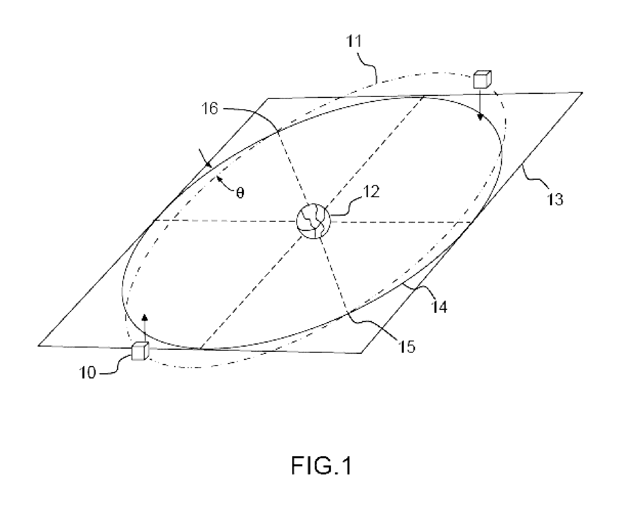
[0095]FIG. 6 represents a satellite with geostationary orbit furnished with propulsion systems in a first embodiment according to the invention. A satellite 100 comprises a first propulsion system 500 fixed to the structure 20 of the satellite 100 by a north side with respect to the plane of the orbit 11, and a second propulsion system 501 fixed to the structure 20 of the satellite 100 by a south side with respect to the plane of the orbit 1. The firing of the propulsion systems 500 and 501 for several positions of the satellite 100 on the orbit 11 allows control of the six orbital parameters of the satellite 100. In the particular case of a geostationary satellite having a parallelepipedal structure, as represented in FIG. 6, the first propulsion system 500 can advantageously be fixed to the structure 20 on the north face 24 and in proximity to the anti-earth face 23, and the second propulsion system 501 can be fixed to the structure 20 on the south face 25 and in proximity to the ...

second embodiment

[0100]FIG. 7 represents a satellite with geostationary orbit furnished with propulsion systems in a second embodiment according to the invention. A satellite 101 comprises a first propulsion system 500 fixed to the structure 20 of the satellite 101 by a north or south side with respect to the plane of the orbit 11, and a second propulsion system 502 fixed to the structure 20 by one and the same side as the first propulsion system 500. The firing of the propulsion systems 500 and 502 for several positions of the satellite 101 on the orbit 11 allows control of the six orbital parameters of the satellite. In the particular case of a geostationary satellite having a parallelepipedal structure, as represented in FIG. 7, the first propulsion system 500 can be fixed to the structure 20 on the north face 24 and in proximity to the anti-earth face 23, and the second propulsion system 502 can be fixed to the structure 20 on the north face 24 and in proximity to the earth face 22.

[0101]The two...


PUM


Abstract

A propulsion system for the orbit control of a satellite with terrestrial orbit having an angular momentum accumulation capacity comprises a propulsion unit able to deliver a force along an axis F having a component perpendicular to the orbit, and a motorized mechanism connected on the one hand to the propulsion unit and on the other hand to a structure of the satellite, the motorized mechanism being able to displace the propulsion unit along an axis V parallel to the velocity of the satellite, and able to orient the propulsion unit so as to make it possible to control: a component of the force along the axis V, for orbit control, an amplitude and a direction of couple in a plane perpendicular to the axis F, for control of the angular momentum.

Description

CROSS-REFERENCE TO RELATED APPLICATION[0001]This application claims priority to foreign French patent application No. FR 1201279, filed on May 3, 2012, the disclosure of which is incorporated by reference in its entirety.TECHNICAL FIELD[0002]The present invention relates to the field of satellite orbit control and attitude control systems, and more particularly the architecture of the on-board propulsion systems for orbit control of geostationary telecommunications satellites.[0003]To allow the use of the various mission instruments of a satellite, such as telecommunications systems, the position and the orientation of the satellite in orbit have to be controllable. In addition to the gravitational attraction of the earth, a satellite experiences several forces of lower magnitudes which progressively disturb its position and its orientation. The gravitational attraction of the sun and moon, the deformation of the earth at the level of the equator, or else the solar radiative pressur...

Claims


Application Information

Patent Timeline
Patent Type & Authority Patents(United States)
IPC IPC(8): B64G1/40B64G1/26B64G1/24
CPCB64G1/409B64G1/242B64G1/26B64G1/405B64G1/413B64G1/264
Inventor CELERIER, BRUNO
Owner THALES SA
Learn More