
Two-layer-three-way catalyst

a three-way catalyst, two-layer technology, applied in the direction of physical/chemical process catalysts, separation processes, arsenic compounds, etc., can solve the problem of not being directly possible, and achieve the effect of further reducing lightoff temperatures and improving thermal stability

Active Publication Date: 2016-12-13
UMICORE AG & CO KG
View PDF15 Cites 21 Cited by
  • Summary
  • Abstract
  • Description
  • Claims
  • Application Information

AI Technical Summary

Benefits of technology

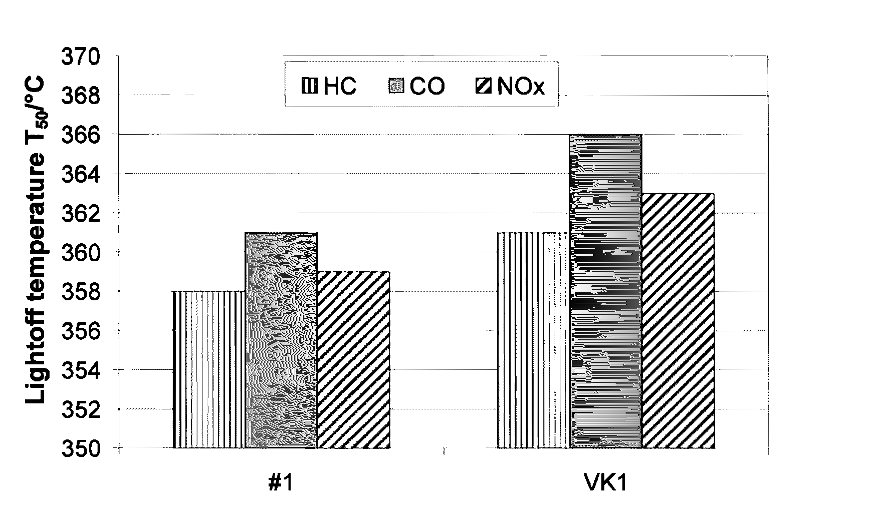
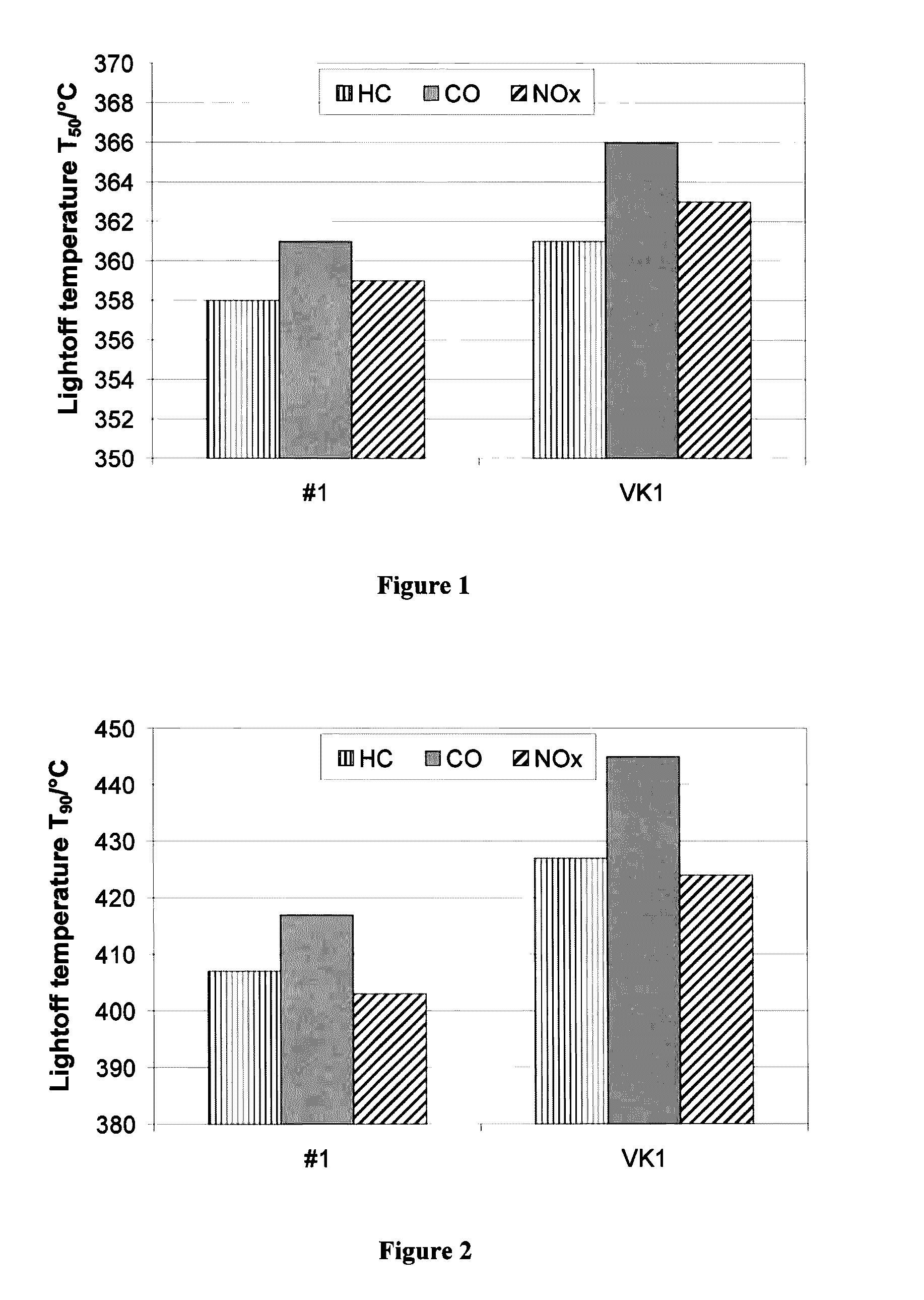
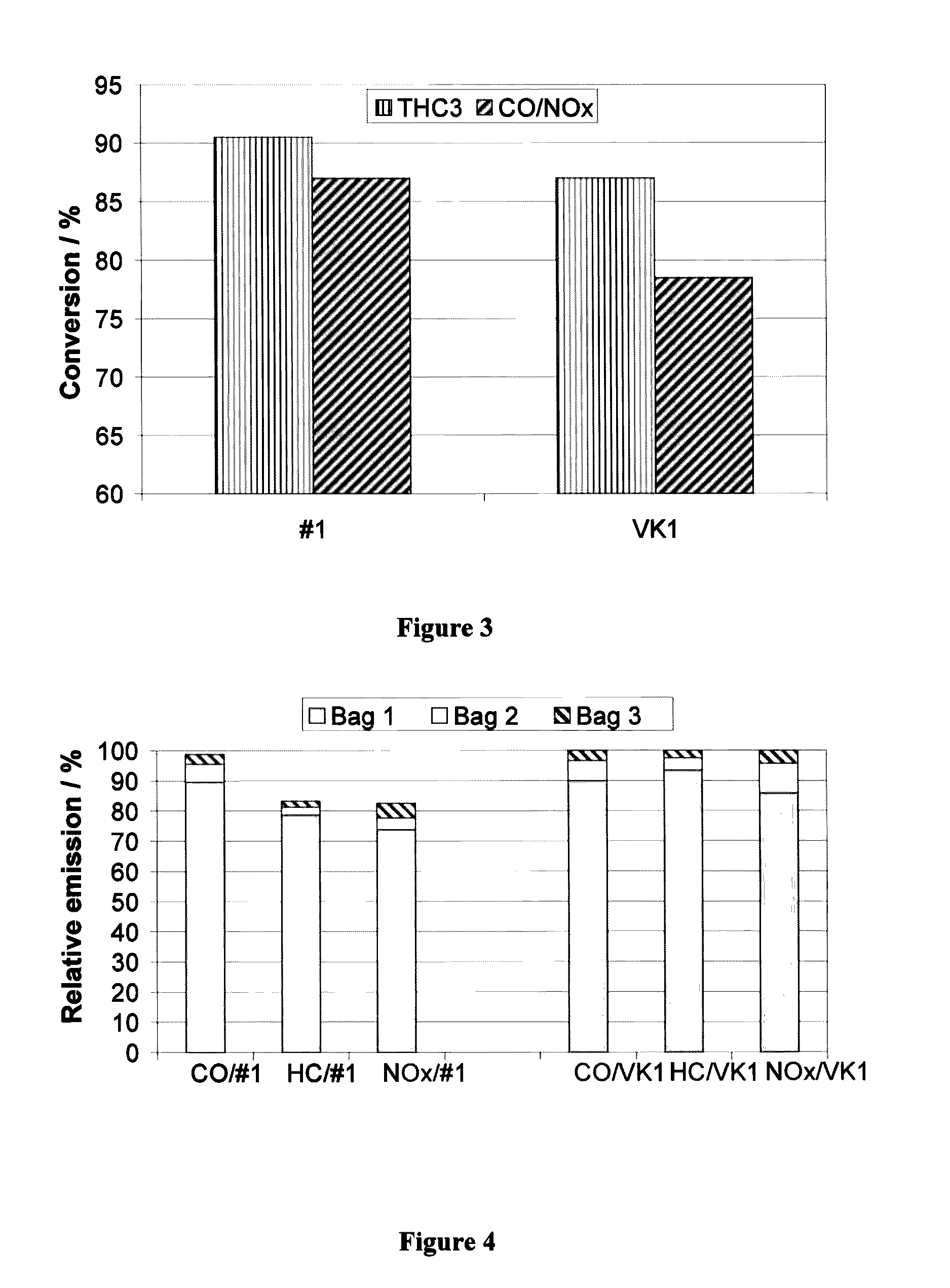
The invention provides a catalyst that has lower lightoff temperatures and improved thermal stability compared to prior art catalysts. This is achieved by stabilizing the active aluminum oxide layers with 1 to 10% by weight of lanthanum oxide. Additionally, the addition of lanthanum oxide or neodymium oxide to the first layer of the catalyst may further improve its performance.

Problems solved by technology

With prior art catalysts, this is not directly possible.

Method used


Image

  • Two-layer-three-way catalyst
  • Two-layer-three-way catalyst
  • Two-layer-three-way catalyst

Examples


example 1

Production of the First Layer:

[0041]An aluminum oxide stabilized with 3% by weight of lanthanum oxide (specific surface area 140 m2 / g) and a cerium / zirconium mixed oxide with a zirconium oxide content of 50% by weight were activated according to U.S. Pat. No. 6,103,660 using strontium hydroxide as the base, together with palladium proceeding from palladium nitrate. The resulting suspension was used directly to coat the honeycombs. After the coating, the honeycombs were dried and calcined. The finished first layer contained the following amounts of coating:

[0042]

76 g / lof lanthanum-stabilized aluminum oxide50 g / lof cerium / zirconium mixed oxide with 50% by weight of ZrO2 2 g / lof strontium oxide (on all components)2.83 g / l  of palladium (on all components)

Production of the Second Layer:

[0043]The lanthanum oxide-stabilized aluminum oxide and a cerium / zirconium mixed oxide with a zirconium oxide content of 70% by weight were suspended in water. Thereafter, an aqueous solution of rhodium n...

example 2

Production of the First Layer:

[0053]The first layer was prepared as described in example 1. After completion, it contained the following amounts of coating:

[0054]

76 g / lof lanthanum-stabilized aluminum oxide50 g / lof cerium / zirconium mixed oxide with 50% by weight of ZrO2 2 g / lof strontium oxide (on all components)0.56 g / l  of palladium (on all components)

Production of the Second Layer:

[0055]The second layer was also produced in the manner described in example 1. The finished second layer contained the following amounts of coating:

[0056]

  65 g / lof lanthanum-stabilized aluminum oxide  65 g / lof cerium / zirconium mixed oxide with 70% by weight of ZrO20.18 g / lof palladium (on all components)0.14 g / lof rhodium (on all components)

[0057]The total noble metal loading of the catalyst #2 thus obtained was 0.88 g / l based on the volume of the honeycomb. The ratio of the concentration of the palladium in the second layer relative to the concentration of the palladium in the first layer, based in ea...


PUM

PropertyMeasurementUnit
concentrationaaaaaaaaaa

Abstract

A double-layer three-way catalyst is presented, which is formed from a catalytic coating applied directly to an inert honeycomb and a catalytically active coating thereon, and is suitable especially for cleaning of exhaust gases of motor vehicles with gasoline-operated internal combustion engines. The catalyst contains, in each layer, an active aluminum oxide and a cerium / zirconium mixed oxide, both of which are catalytically activated by palladium. The second layer on the gas side contains not only palladium but also rhodium, which is applied to the active aluminum oxide and the cerium / zirconium mixed oxide of the second layer in addition to the palladium. The cerium / zirconium mixed oxide of the second layer has a higher zirconium oxide content than the cerium / zirconium mixed oxide of the first layer. The catalyst is notable for exceptional activity coupled with outstanding aging stability.

Description

[0001]This application claims the benefit of International Application PCT / EP2008 / 001216 filed Feb. 16, 2008 and EP Application 07005547 filed Mar. 19, 2007 which are relied on and incorporated herein by reference.INTRODUCTION AND BACKGROUND[0002]The invention relates to a three-way catalyst which is formed from two superposed catalytically active layers, is suitable for the cleaning of the exhaust gases of internal combustion engines, and has outstanding catalytic activity coupled with exceptional thermal aging stability.[0003]Three-way catalysts are used in large numbers for the cleaning of the exhaust gases of internal combustion engines operated under essentially stoichiometric conditions. They are capable of converting the three significant gaseous pollutants of the engine, specifically hydrocarbons, carbon monoxide and nitrogen oxides, simultaneously to harmless components. Double-layer catalysts are frequently used, which enable a separation of different catalytic processes a...

Claims


Application Information

Patent Timeline
Patent Type & Authority Patents(United States)
IPC IPC(8): B01J23/00B01J21/00B01J25/00B01J23/10B01J29/00B01J23/63B01J37/02B01D53/94B01J23/44B01J23/46
CPCB01J37/0244B01D53/945B01J23/63B01D2255/1021B01D2255/1023B01D2255/1025B01D2255/2042B01D2255/407B01D2255/9022B01J23/44B01J23/464Y02T10/22Y02A50/20Y02T10/12B01J23/46B01J37/02B01D53/94
Inventor ROESCH, MARTINLINDER, DIETERKLINGMANN, RAOULDE COLA, PATRIZIA LAURARICHTER, JOERG-MICHAELSCHMIDT, MARCUS
Owner UMICORE AG & CO KG
Learn More