
Method of delivering medical gases via a nasal cannula assembly with flow control passage communicating with a deformable reservoir

a technology of flow control passage and nasal cannula, which is applied in the direction of respiratory devices, medical devices, other medical devices, etc., can solve the problems of limiting the portability of the system, increasing the size of the system, and delivering the pulse, so as to minimize the exhalation of no, minimize the size of the system, and minimize the effect of the delivery

Active Publication Date: 2016-12-13
LAIR LIQUIDE SA POUR LETUDE & LEXPLOITATION DES PROCEDES GEORGES CLAUDE
View PDF58 Cites 3 Cited by
  • Summary
  • Abstract
  • Description
  • Claims
  • Application Information

AI Technical Summary

Benefits of technology

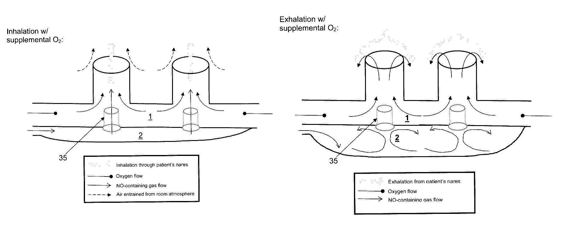
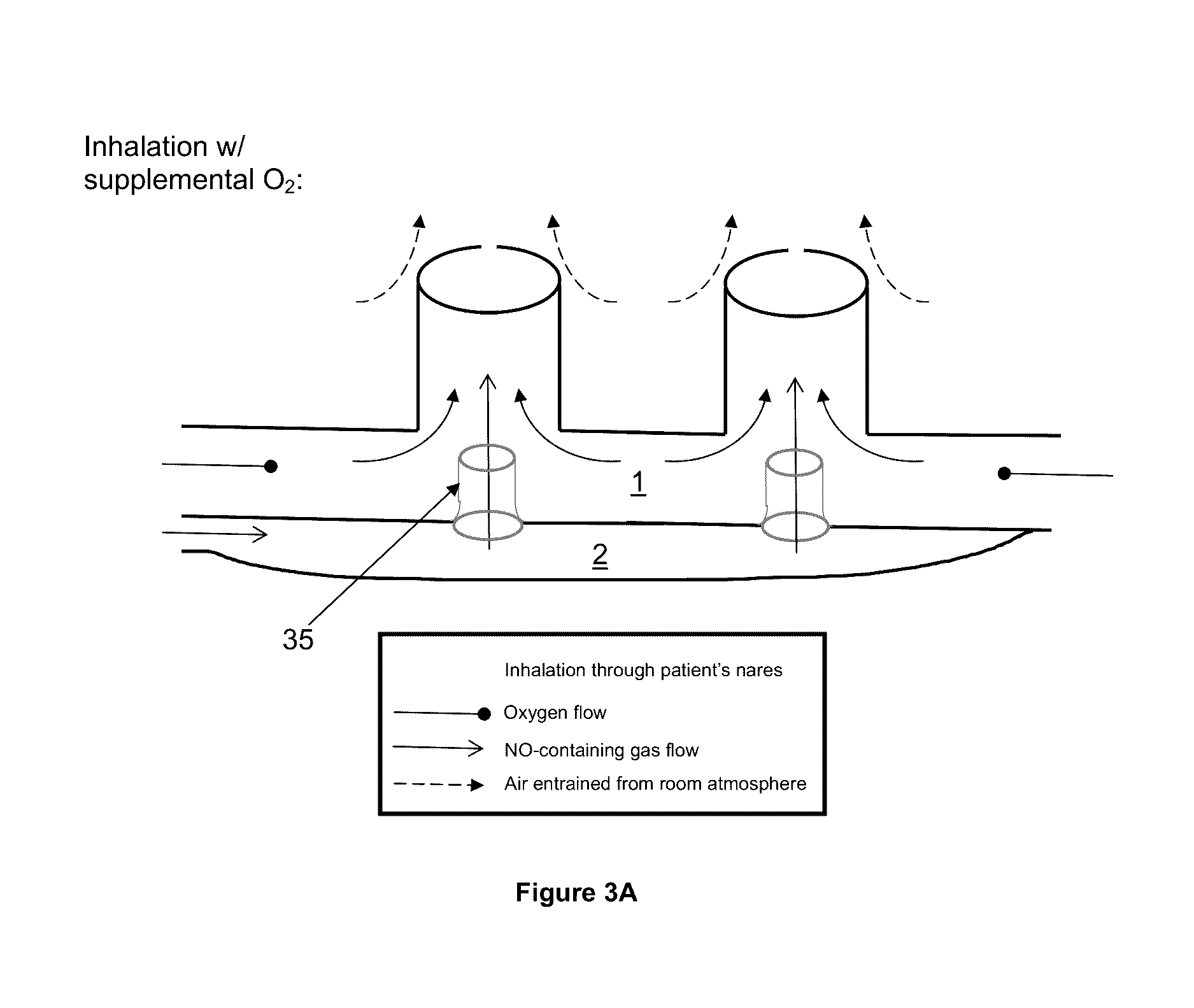
[0020]A main goal of the invention is to provide a delivery system convenient for use by ambulatory patients, which allows nitric oxide (NO) to be efficiently administered over extended time periods, i.e. hours, days, weeks, through nasal prongs in a manner that minimizes delivery into the anatomical dead volume at the end of inhalation, and therefore also minimizes exhalation of NO. In so doing, the system must avoid bringing NO-containing gas into contact with oxygen-containing gas until just prior to delivery to the patient, so as to avoid or minimize production of toxic NO2 gas through reaction of NO with oxygen.
[0082]b) providing a therapeutically-effective amount of a NO-containing gas to said patient through said nasal cannula assembly for inhalation to thereby reduce the pulmonary vasoconstriction in the patient.27. The method according to Numbered Sentence 26, wherein the patient is an adult, an infant or a newborn.28. The method according to Numbered Sentence 26, wherein pulmonary vasoconstriction is associated with persistent pulmonary hypertension of the newborn.29. The method according to Numbered Sentence 26, wherein pulmonary vasoconstriction is associated with pulmonary arterial hypertension.30. The method according to Numbered Sentence 26, wherein the NO-containing gas is mixed with an oxygen-containing gas just before being inhaled by the patient.31. The method according to Numbered Sentence 26, wherein the NO-containing gas is a NO / nitrogen mixture.32. The method according to Numbered Sentence 26, wherein the NO-containing gas consists in a NO / nitrogen mixture containing from 1 ppm to 5000 ppmv of NO.33. The method according to Numbered Sentence 26, wherein the O2-containing gas is air or an O2 / N2 mixture containing at least 21% (by volume) of O2.

Problems solved by technology

If adapted for NO delivery to ambulatory patients, such systems suffer from the requirements of a source of electrical power and the need for electromechanical parts to sense and administer sequenced pulses of NO, both of which increase the size of the system, and limit its portability.
In addition, due to inevitable lags in timing between detection of the start of patient inhalation and operation of dosing valves, these systems risk delivering their pulses too late in the inhalation, such that a significant fraction of NO is exhaled.
This type of reservoir cannula has found utility in supplying supplemental oxygen to patients, but is ill-suited for supplying patients with NO / nitrogen gas mixtures in place of oxygen.
First, reservoir cannulas as previously described contain means to connect to only a single source of gas; however because commercial NO / nitrogen gas mixtures contain no oxygen, patients may require an additional source of supplemental oxygen.
Second, even if air entrained from the room during inhalation provides sufficient oxygen to meet a patient's demand, it is not acceptable that oxygen-containing gas exhaled by the patient mix with NO-containing gas supplied to the chamber.
For commonly supplied concentrations of medical NO / nitrogen gas mixtures (e.g. containing 800 ppm NO in balance nitrogen) this delivered volume risks exposing the patient to too high a concentration of NO and too low a concentration of oxygen, especially for younger patients with tidal volumes less than ˜200 ml, or for adult patients exhibiting rapid, shallow breathing.

Method used


Image

  • Method of delivering medical gases via a nasal cannula assembly with flow control passage communicating with a deformable reservoir
  • Method of delivering medical gases via a nasal cannula assembly with flow control passage communicating with a deformable reservoir
  • Method of delivering medical gases via a nasal cannula assembly with flow control passage communicating with a deformable reservoir

Examples


working example

[0130]To demonstrate an embodiment of the restriction flow channel of the invention, a mechanical lung simulation device was used to produce a breathing pattern. The breathing pattern was set to that of an average adult human. Breathing patterns representing any patient could be used as the basis for validating a restriction flow channel design for a specific class of patients (e.g. pediatric breathing patterns). The exemplary experiment was performed using a single flow restriction channel [35a] positioned between a first compartment [1] and a second compartment [2]. A 22 mm diameter straight connector [22] including a port for gas sampling via the gas sampling line [30] was positioned between a lung simulator (ASL 5000; Ingmar Medical) [40] and T piece [21]. A second arm of the T piece [21] was connected to a 22 mm straight connector [23], which contained internally a 4 mm flow restriction channel [35a]. The third arm of the T piece [21] was either left open to the room atmosphere...


PUM


Abstract

The invention concerns a nasal cannula assembly (10) adapted to deliver gases to a patient comprising a first compartment (1) and a second compartment (2) separated by a separation wall (6); a pair of nasal prongs (5) in fluid communication with the first compartment (1); the first compartment (1) comprising a first inlet (11) for introducing a first gas into said first compartment (1); the second compartment (2) comprising a second inlet (2) for introducing a second gas into said second compartment (2); and the separation wall (6) comprising at least one flow restriction element (35) for controlling the passage of gas from the second compartment (2) to the first compartment (1).

Description

BACKGROUND OF THE INVENTION[0001]Field of the Invention[0002]The invention concerns a nasal cannula assembly adapted to deliver gases to a patient, especially for NO gas therapy, a breathing assistance apparatus comprising such a nasal cannula assembly, and a method for treating pulmonary vasoconstriction in a patient using such a nasal cannula assembly and / or breathing assistance apparatus.[0003]Description of the State of the Art[0004]NO / nitrogen gas mixtures are commonly used for treating vasoconstrictions of the lung and pulmonary hypertension in adults and infants.[0005]For instance, EP-A-1516639 discloses a gaseous mixture consisting of NO and an inert gas, preferably nitrogen, used for the production of an inhalable medicament for treating persistent pulmonary hypertension of the newborn.[0006]Before being inhaled by the patient, the NO / N2 mixture is generally diluted in an oxygen-containing gas, such as air or a O2 / N2 mixture, comprising at least 21 vol. % of oxygen.[0007]Ty...

Claims


Application Information

Patent Timeline
Patent Type & Authority Patents(United States)
IPC IPC(8): A61M16/06A61M16/10A61M16/12A61M16/20A61M16/08
CPCA61M16/0672A61M16/0666A61M16/0866A61M16/122A61M16/125A61M16/208A61M2202/0208A61M2202/0275A61M2209/02
Inventor MARTIN, ANDREW
Owner LAIR LIQUIDE SA POUR LETUDE & LEXPLOITATION DES PROCEDES GEORGES CLAUDE
Learn More