Method and device for controlling an inverter

a technology of inverter and control device, which is applied in the direction of electric generator control, dynamo-electric converter control, dynamo-electric gear control, etc., can solve the problem of generally long service life of inverter, and achieve the effect of constant torque and even load

Active Publication Date: 2016-12-06
ROBERT BOSCH GMBH
View PDF14 Cites 3 Cited by
  • Summary
  • Abstract
  • Description
  • Claims
  • Application Information

AI Technical Summary

Benefits of technology

[0012]Owing to the fact that the current space vector is provided with a phase angle which is different from the nominal phase angle, in certain situations in which the controllable switch is overloaded, in particular thermally overloaded, or threatens to become overloaded, it is possible to relieve one of the controllable switches, by a current space vector with a phase angle being set which relieves the overloaded controllable switch and loads another controllable switch more heavily. As a result, the loading of the controllable switches can be varied and thus the inverter can be more evenly loaded. Thus, as a result, the switches can be loaded according to a nominal loading value, even for critical phase angles of the required current space vector. Thus, the controllable switches can be configured, in general, for lower loading values, as a result of which the inverter can generally be manufactured in a technically less elaborate and more cost-effective manner. Furthermore, by means of the more even loading of the switches, the service life of the inverter is generally lengthened.
[0039]As a result, by means of the present invention, the inverter can be evenly loaded, even in the case of low rotation frequencies of the current space vector, by a current space vector being set of which the phase angle deviates from the nominal phase angle, wherein, despite the changed phase angle, a constant torque is provided in particular in the case of control of electrical machines.

Problems solved by technology

Furthermore, by means of the more even loading of the switches, the service life of the inverter is generally lengthened.

Method used


Image

  • Method and device for controlling an inverter
  • Method and device for controlling an inverter
  • Method and device for controlling an inverter

Examples


Embodiment Construction

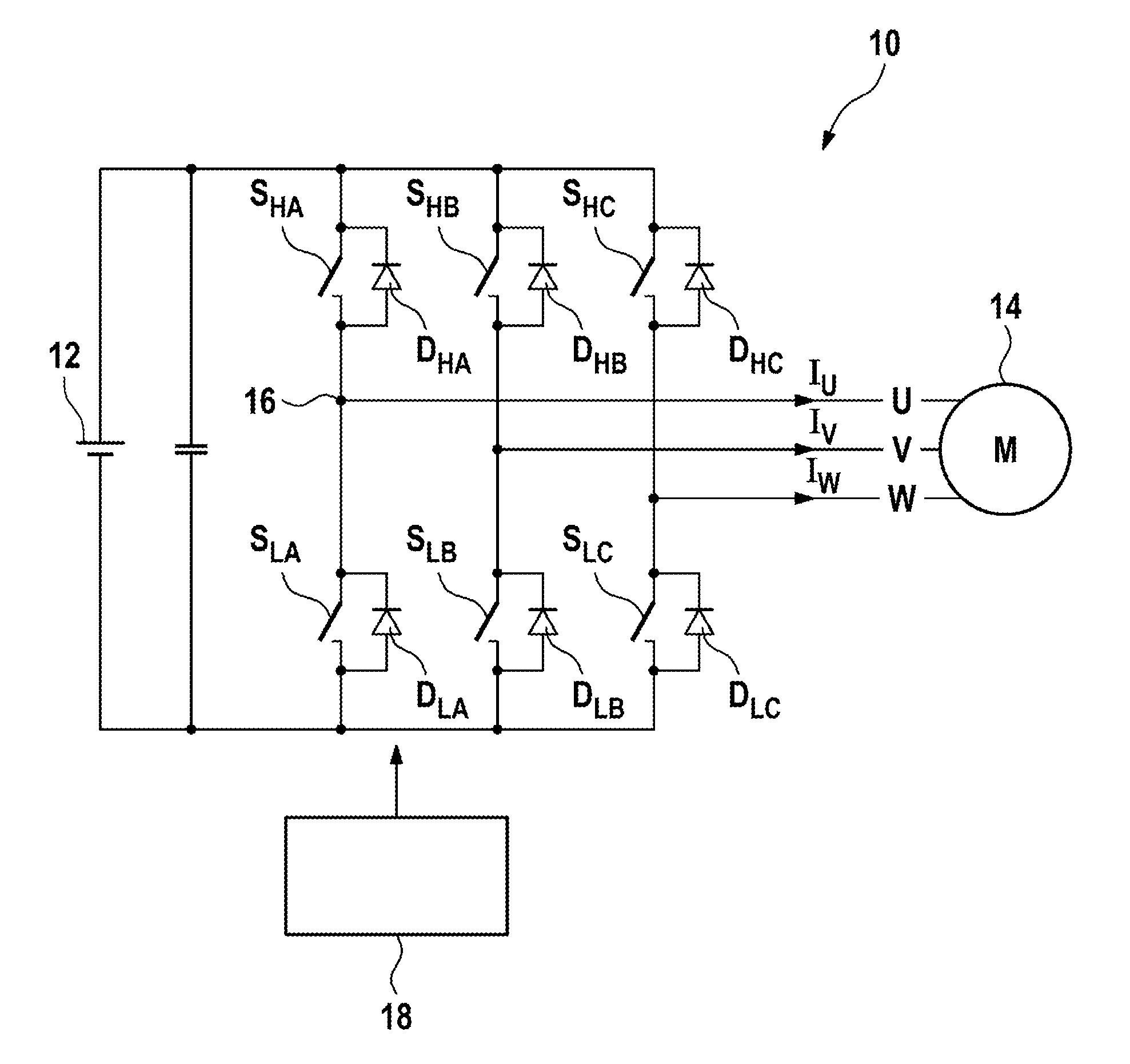
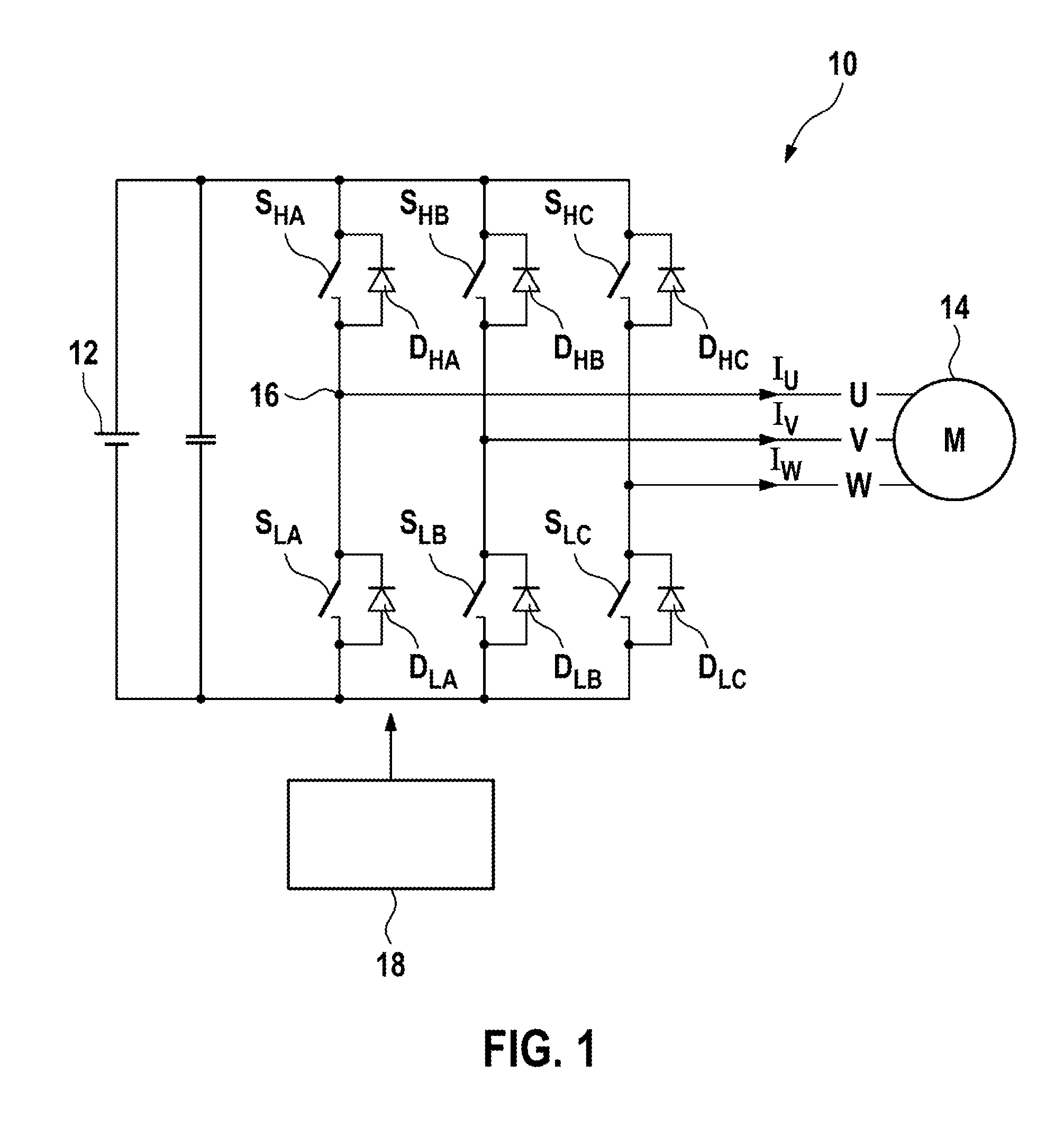
[0049]FIG. 1 schematically illustrates an inverter for controlling an electrical load, in particular an electrical machine, which inverter is generally denoted by 10.

[0050]The inverter 10 is connected to a DC voltage source 12 and is used to energize the electrical load 14, which in this case is designed as an electrical machine 14, in a three-phase fashion. The inverter has three half-bridges which are connected in parallel with the DC voltage source 12 and have in each case two controllable switches S. Between the switches S, a half-bridge tap 16 is formed in each case, which half-bridge taps are each connected to a phase conductor of the phases U, V, W of the electrical machine 14.

[0051]In each case, a freewheeling diode D which enables a flow of current in the opposite direction is connected in parallel with the switches S.

[0052]In FIG. 1, the switches S are denoted by SHA, SLA, SHB, SLB, SHC, SLC corresponding to the phase U, V, W which they provide and corresponding to the ass...


PUM


Abstract

The invention relates to a method for controlling an inverter (10) using space-vector pulse width modulation, in particular to control an electric machine (14), the inverter (10) being equipped with a plurality of controllable switches (S) and being designed to provide a polyphase electric current (IU, IV, IW), in particular to supply polyphase electric current (IU, IV, IW) to the electric machine (14). In said method, a desired current space vector (I1*) having a desired phase angle (alpha1) and a desired amplitude (I1) is predefined, and the inverter (10) is controlled in such a way that a plurality of different successive switching states (V0-V7) is established for the switches (S) in order to provide the electric current (IU, IV, IW) in the form of a current space vector (I*), the inverter (10) being controlled in such a way that the current space vector (I2*) is provided at a phase angle (alpha2) which differs from the desired phase angle (alpha1) in order to load the switches (S) according to a desired load value (m) for the switches (S).

Description

BACKGROUND OF THE INVENTION[0001]The present invention relates to a method for controlling an inverter by means of space vector modulation, in particular for controlling an electrical machine, wherein the inverter has a plurality of controllable switches and is designed to provide a polyphase electric current, in particular in order to supply the electrical machine with electric current in a polyphase manner, wherein a nominal current space vector having a nominal phase angle and a nominal amplitude is predefined, wherein the inverter is controlled such that a plurality of different consecutive switching states of the switches are set in order to provide the electric current in the form of a current space vector.[0002]The present invention also relates to a device for controlling an inverter, in particular for controlling an electrical machine, wherein the inverter has a plurality of controllable switches which are connected to provide a polyphase electric current on the basis of a ...

Claims


Application Information

Patent Timeline
Patent Type & Authority Patents(United States)
IPC IPC(8): H02P21/00H02M7/46H02P29/00H02M7/5395H02P27/08H02M1/32
CPCH02M7/46H02M7/5395H02P21/22H02P29/68H02M2001/327H02P27/08H02P2205/01H02M1/327
Inventor HIRSCH, MICHELESCHUSTER, ULRICHMERKEL, TINODEFLORIO, ANDREA
Owner ROBERT BOSCH GMBH
Why Eureka
Try Eureka