Radial-parallel catalytic reactor

a catalytic reactor and radial parallel technology, applied in chemical/physical/physical-chemical stationary reactors, chemical apparatus and processes, chemical/physical/physical-chemical processes, etc., can solve the problems of destroying the adiabatic conditions of the catalyst layer, affecting the catalytic activity and lifespan, and unable to meet the requirements of further scale-up production, etc., to improve the catalyst activity and lifespan, simplify the heat transfer process, and the operation work of the added apparatus is relatively simpl

Inactive Publication Date: 2016-11-29
ZHANG HUAIHAI +1
View PDF6 Cites 1 Cited by
  • Summary
  • Abstract
  • Description
  • Claims
  • Application Information

AI Technical Summary

Benefits of technology

[0011]The present invention provides an axial radial reactor which is easy to scale up or down in process gas flows, stable at work and simple to operate.
[0027]The present utility model employs a parallel structure of catalyst beds, and combines a new type of interlayer thermal transfer structure outside of the catalyst beds, thus constituting a novel multi-stage radial-parallel multi-bed-layer reactor which utilizes the characteristics of parallel catalyst beds and thus can have the following advantages: because the catalyst beds are in parallel, reactants at each stage of the catalyst beds are separately discharged outside the reactor, thus avoiding the reactants from entering into a next stage of the catalyst beds for repeated reaction; since the reactants do not reach a next stage of the catalyst beds, reaction heat is not accumulated at a next stage, thus simplifying the heat transfer process and means; the reaction process at each stage is the same, therefore the operation work of the added apparatus is relatively simple, this is beneficial to scale-up of the multi-bed-layer radial reactor.
[0028]The described multi-stage radial-parallel multi-bed-layer reactor utilizes a heat insulation means disposed in an annular gap between multi-bed-layers to regulate and control the reaction mass that has been exported from the catalyst layers, and can have the following advantages: the regulation and control of the reaction mass is performed outside of the catalyst layers, this avoids the influence of the regulation and control device as well as the introduced fluid on the catalytic activity, thus improving the catalyst activity and lifespan, and avoids the influence of the regulation and control device as well as the introduced fluid on uniform distribution of reaction mass and uniform temperature within the reaction layers, thus simplifying the reactor design, and avoids adverse consequences that bad distribution of reaction mass in a previous layer is accumulated to a next stage; by individual or combination use of the following various embodiments, a wide-range regulation and control of the physical state and chemical composition of the reaction mass can be performed, and approaches are relatively simple and have a stable effect; the present utility model meets the requirements of scale-up of a multi-bed-layer radial reactor, and has simple structure, easy operation and stable work, which is beneficial to improvement of the quality of the reactor operation and improvement of product quality.

Problems solved by technology

Such multi-stage design provides a good solution for the demands of structure and process in scale-up of a reactor, however, when adopting a multi-bed-layer design, this approach faces the following problems: axial multi-stage technology leads to unrepeatable overlay of catalyst beds due to catalyst bed installation sequence, therefore it is unable to meet the requirements of further scale-up production; in applications of a multi-bed-layer radial reactor, because of its inability to adopt a multi-stage design, it usually has a cooling tube with / without an opening buried in the catalyst layers, so as to transfer reaction heat with coolant or quench fluid, but it destroys adiabatic conditions of the catalyst layers.
The presence of cooling tube and quench fluid makes flow field and temperature distribution become very complex, causing a significant adverse effect on catalytic activity and lifespan; moreover, the regulation and control of coolant or quench fluid is very difficult.
However, careful consideration of these arrangements, as one skilled in the art would do, allows a designer to understand limitations of unwarranted applications for features of one radial reactor to another, where either process, mechanical or structural requirements of a specific application create such practical obstacles.
The arrangement is especially ineffective, in that inadequate turbulent flow is achieved to achieve radial uniformity in temperature or quench gas mixing.
This design similarly is disabled as to uniformity of gas composition and temperature across a horizontal cross section thereof, as there is insufficient space for such uniformity to develop.
The disability of this design is apparent to one skilled in the art, in that the spaced apart pipes used for injection of quench gas create cooled vertical zones separated by hot vertical zones due to inadequate mixing of gas from one reactor flowing immediately and without adequate mixing straight into the next catalyst bed.
U.S. Pat. No. 2,517,525 discloses a design similar to that of the '804 patent, in that it is not capable of having additional radial flow catalyst beds added above or below the single level of radial flow catalyst beds.
This design still suffers the disability of failing to provide adequate space volume in which uniform compositions and temperatures of the gas in horizontal cross section may be achieved before the gas flows to the next radial catalyst bed.

Method used


Image

  • Radial-parallel catalytic reactor
  • Radial-parallel catalytic reactor
  • Radial-parallel catalytic reactor

Examples


example 1

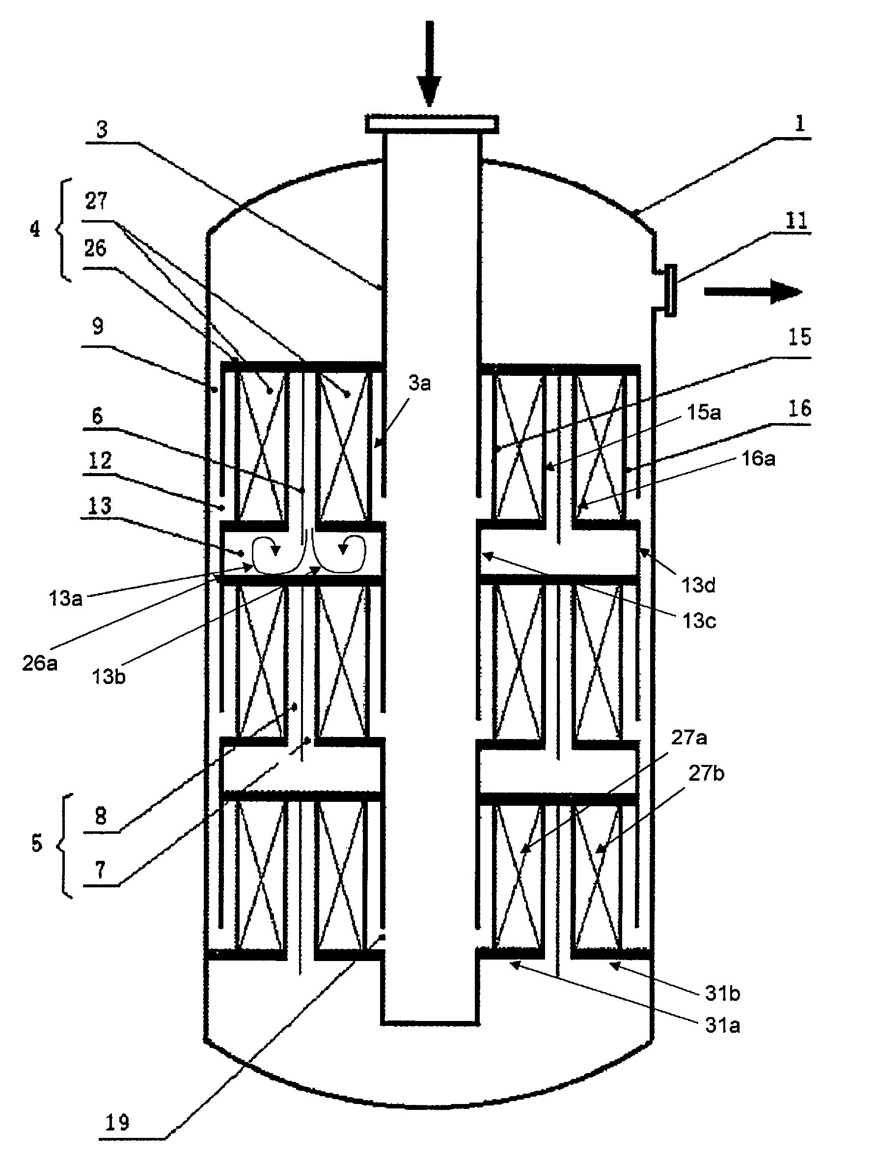
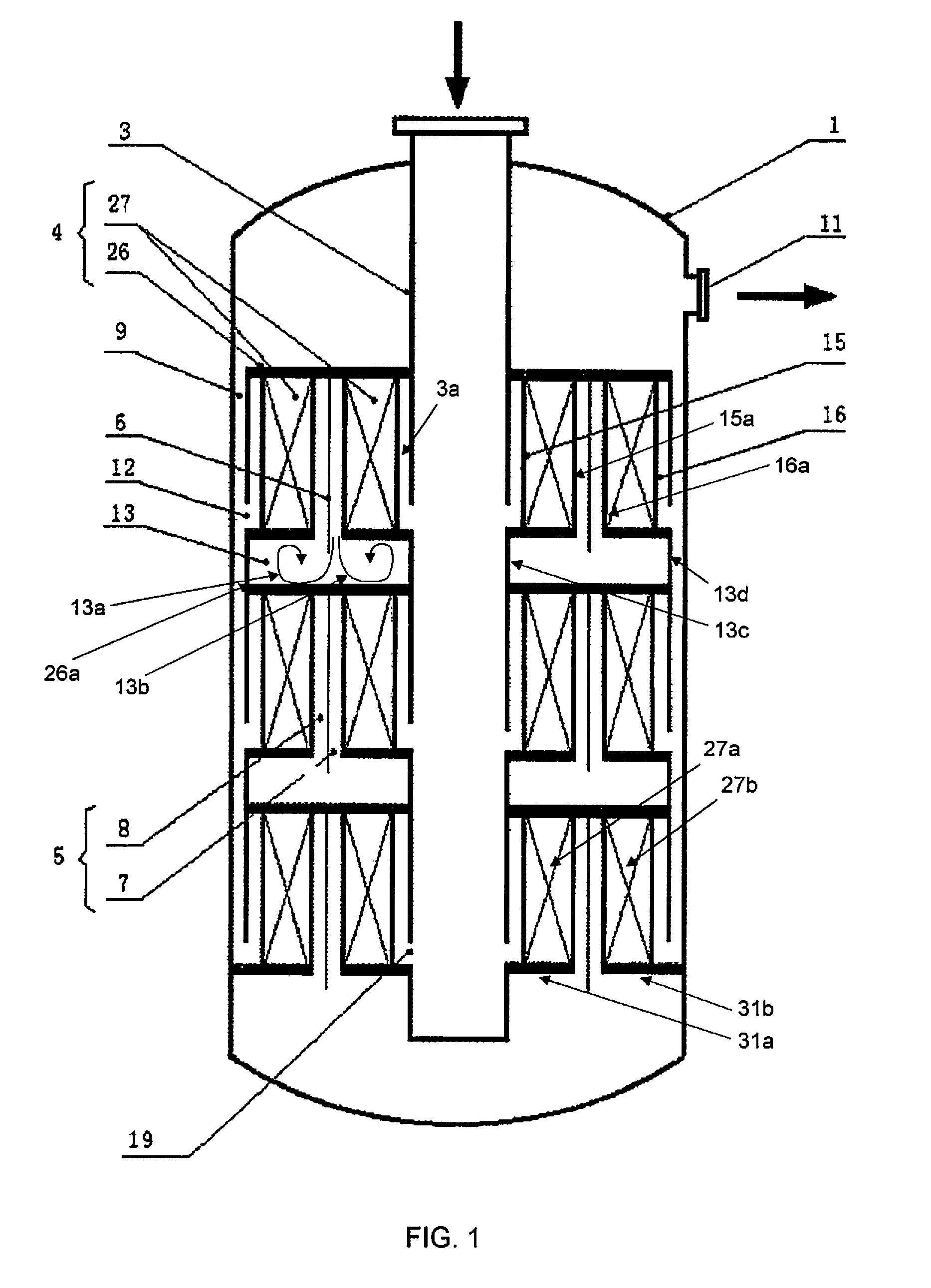
[0038]With reference to FIG. 1, it shows a radial-parallel catalytic reactor according to one embodiment of the present utility model, comprising a reactor shell 1 and three axially juxtaposed radial catalytic-reaction beds 4 along a feed tube 3 in the shell 1; each radial catalytic-reaction bed 4 has an inner perforated plate 15 in communication with the feed tube 3; an inlet 19 of the feed tube is provided at an appropriate position of the feed tube 3, and the inlet 19 together with the inner perforated plate 15 of the radial catalytic-reaction bed 4 forms a gas-distribution channel.

[0039]In this embodiment, each radial catalytic-reaction bed 4 is divided into two bed layers 27, and the bed layers 27 in a same radial catalytic-reaction bed 4 have a common top plate 26; the bed layers are filled with the same or different catalysts, depending on reaction requirements, which may include ammonia synthesis, hydrocarbon catalytic reactions, or similar large scale industrial processes. ...

example 2

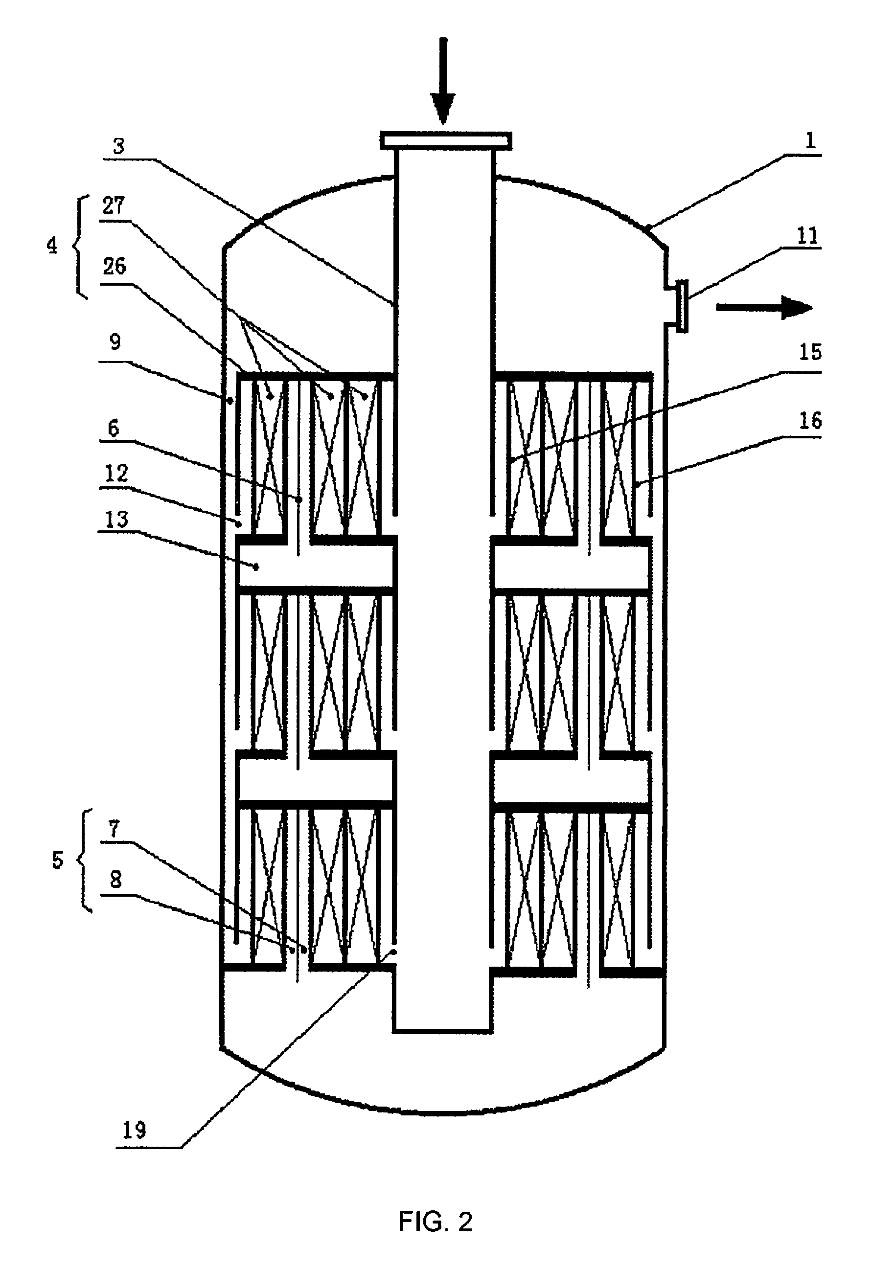
[0044]With reference to FIG. 2, the radial-parallel catalytic reactor in this embodiment is substantially the same as the one in Example 1, except that the reactor in this embodiment comprises a catalytic-reaction bed 4 having three bed-layers, wherein an annular gap is provided between second reaction bed-layer and third reaction bed-layer along a flow direction of reaction mass.

[0045]Similarly, depending on actual reaction needs, an annular gap may be provided between first and second reaction bed-layers or between each reaction bed-layer along the flow direction of reaction mass.

[0046]Likewise, the present utility model may comprise a plurality of reaction bed-layers and a plurality of annular gaps between the bed-layers. For clarity, the variants are not described here in detail. It should be understand by the skilled in the art that the variants of these embodiments all fall in the scope of the present utility model as claimed.

example 3

[0047]With reference to FIG. 3, the radial-parallel catalytic reactor in this embodiment is substantially the same as the one in Example 1, except that the reactor in this embodiment uses an external tube 28 as a substitute for the interlining 9 to discharge the reaction products.


PUM


Abstract

The present invention comprises an axial radial catalytic reactor with a shell (as gas tight seal to maintain process gas flows within it) and a feed tube (passing from a source of process gas flow through the shell and into it do deliver feed gas to one or more levels of two annularly sequential catalyst beds), where one end of the feed tube is used as an inlet for feeding reaction mass. In one embodiment of the invention, an interior end of the feed tube is sealed.

Description

[0001]The present application is related to and claims the benefit under 35 U.S.C. §119(a) to a Chinese Patent Application No. 201420287439.2 filed on May 30, 2014 in the Peoples' Republic of China, the entire disclosure of which is hereby incorporated by reference.FIELD OF THE INVENTION[0002]The present utility model relates to a chemical catalytic reactor, especially to a multi-stage radial-parallel-multi-bed-layer reactor.BACKGROUND OF THE INVENTION[0003]Currently, large radial reactors have been widely used. For consideration of structure and process, such a reactor in scale-up usually has its catalyst bed divided into multi stages and separately placed into a same shell. Each stage has separation space formed therebetween, and reaction mass passes through a gas-collection channel of a catalyst bed along a radial direction, and moves downward along an axial direction, then passes through the separation space into a gas-distribution channel of a catalyst bed at a next stage. In t...

Claims


Application Information

Patent Timeline
Patent Type & Authority Patents(United States)
IPC IPC(8): B01J8/00B01J8/02B01J8/04B01J19/00B01J19/24
CPCB01J8/0411B01J8/001B01J8/0492B01J8/0496B01J2208/0092B01J2208/00194B01J2208/00548B01J2208/00823B01J2208/00849B01J2208/00893B01J2208/00938B01J2208/027B01J2219/00038
Inventor ZHANG, HUAIHAIZHAO, SHIYU
Owner ZHANG HUAIHAI
Why Eureka
Try Eureka