
Plasma processing apparatus and plasma processing method

a processing apparatus and plasma technology, applied in the direction of plasma technique, electrical apparatus, electric discharge tubes, etc., to achieve the effect of reducing the increase in the cost of the apparatus and expanding the plasma generation area

Active Publication Date: 2016-11-22
TOKYO ELECTRON LTD
View PDF6 Cites 2 Cited by
  • Summary
  • Abstract
  • Description
  • Claims
  • Application Information

AI Technical Summary

Benefits of technology

[0008]More specifically, embodiments of the present invention provide a plasma processing apparatus and a plasma processing method that can expand a plasma generation area when seen in a plan view while reducing an increase in costs of the apparatus in performing a plasma process on a rotating substrate.

Problems solved by technology

However, Japanese Laid-Open Patent Application Publication No. 2011-119659 and Japanese Laid-Open Patent Application Publication No. 2003-22977 do not disclose a wafer rotation type apparatus and plasma distribution thereof.

Method used


Image

  • Plasma processing apparatus and plasma processing method
  • Plasma processing apparatus and plasma processing method
  • Plasma processing apparatus and plasma processing method

Examples


working examples

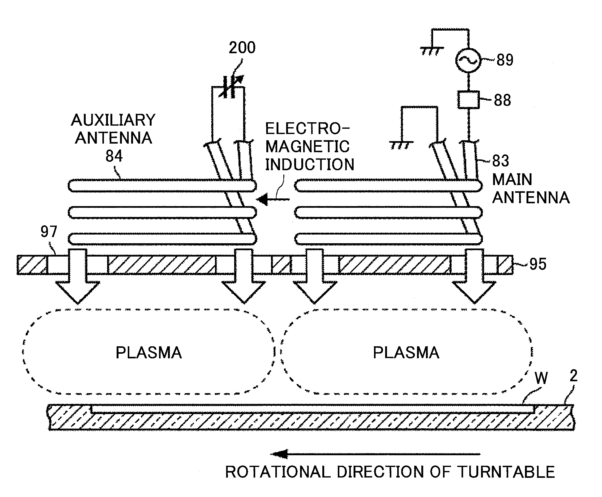
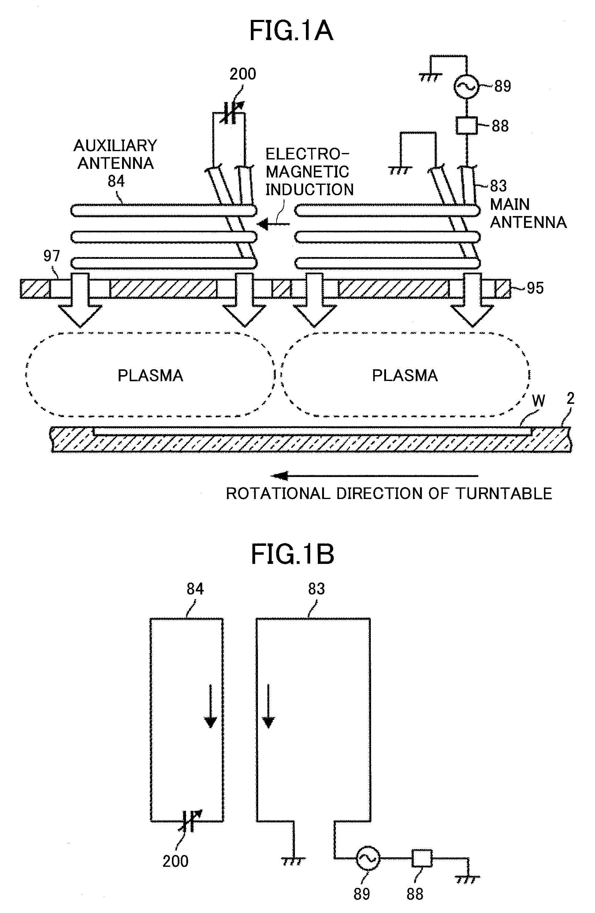
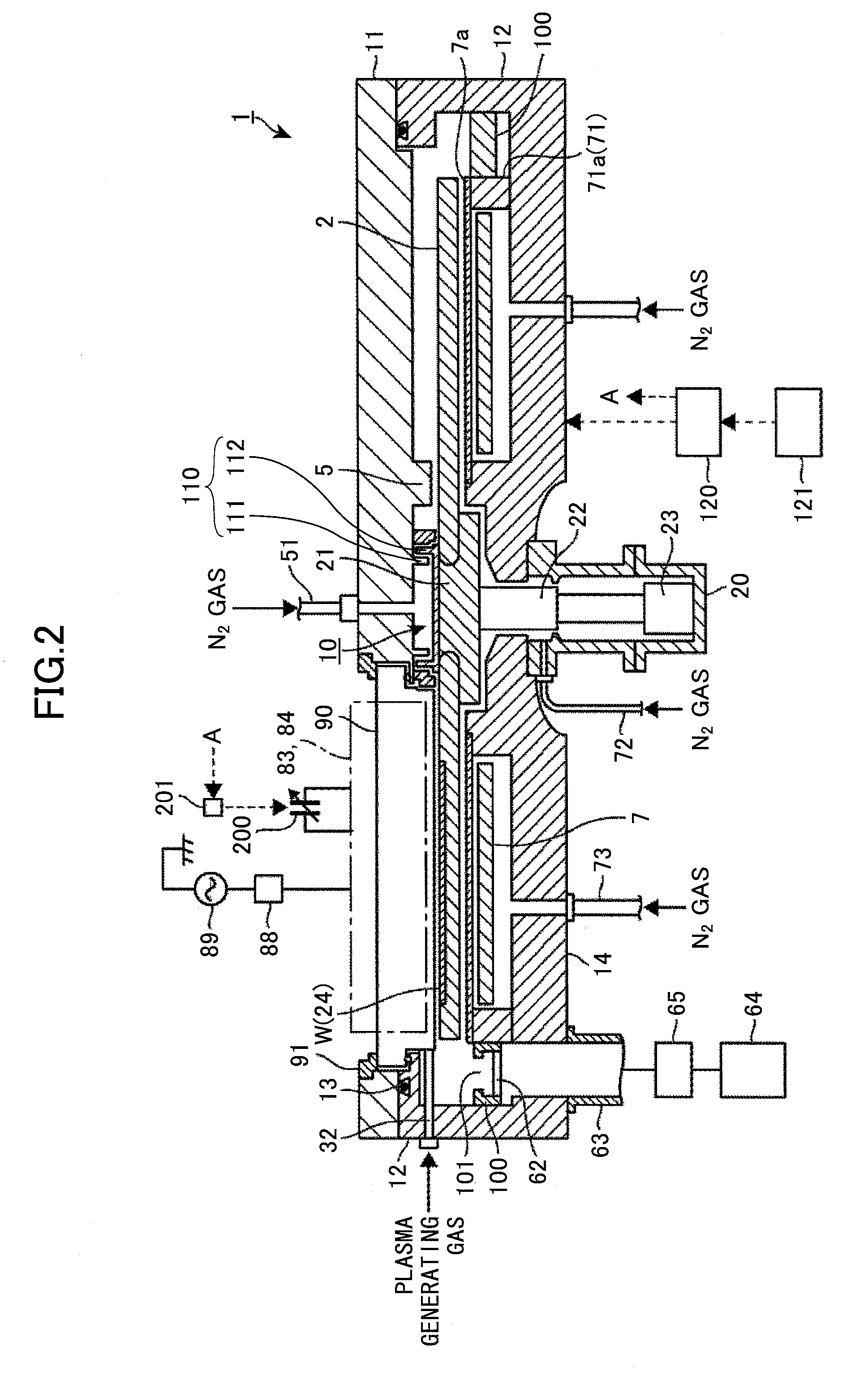
[0092]Subsequently, a description is given below of an experiment performed to confirm that plasma is generated under the antennas 83 and 84. As illustrated in FIG. 16, this experiment was performed by arranging amain antenna 83 formed to have an approximate rectangle when seen in a plan view and an auxiliary antenna 84 formed to have an approximate quadrangle at a position close to the main antenna 83 within an experimental chamber. In this example, in order to construct the main antenna 83 whose capacitance value is adjustable, a capacitance adjusting part 201 was arranged between an end in the lengthwise direction of the main antenna 83 and the high frequency power source 89, and a capacitance adjusting part 202 was also arranged between the other end of the auxiliary antenna 84 and the earth. In addition, the capacitance adjusting part 200 was arranged in the auxiliary antenna 84.

[0093]Then, the capacitance value of the capacitance adjusting part 200 in the auxiliary antenna 84 ...


PUM


Abstract

A plasma processing apparatus is provided. According to the apparatus, a main antenna connected to a high frequency power source and an auxiliary antenna electrically insulated from main antenna is arranged. Moreover, projection areas when the main antenna and the auxiliary antenna are seen in a plan view are arranged so as not to overlap with each other. More specifically, the auxiliary antenna is arranged on a downstream side in a rotational direction of the turntable relative to the main antenna. Then, a first electromagnetic field is generated in the auxiliary antenna by way of an induction current flowing through the main antenna, and a second induction plasma is generated even in an area under the auxiliary antenna in addition to an area under the main antenna by resonating the auxiliary antenna.

Description

CROSS-REFERENCE TO RELATED APPLICATIONS[0001]This patent application is based upon and claims the benefit of priority of Japanese Patent Application No. 2013-236013, filed on Nov. 14, 2013, the entire contents of which are incorporated herein by reference.BACKGROUND OF THE INVENTION[0002]1. Field of the Invention[0003]The present invention relates to a plasma processing apparatus and a plasma processing method that perform a plasma process on a substrate.[0004]2. Description of the Related Art[0005]A semi-batch type apparatus disclosed in Japanese Laid-Open Patent Application No. 2013-45903 is known as an apparatus that performs a plasma process on a substrate such as a semiconductor wafer (hereinafter, “wafer”). More specifically, in Japanese Laid-Open Patent Application No. 2013-45903, five wafers are located on a turntable in a circumferential direction thereof, and an antenna for generating plasma from a gas is arranged so as to face a track of the wafers moving (rotating) by th...

Claims


Application Information

Patent Timeline
Patent Type & Authority Patents(United States)
IPC IPC(8): H01J37/32
CPCH01J37/3211H01J37/321H01J37/32651H01J37/32183
Inventor KATO, HITOSHIMIURA, SHIGEHIROKOSHIMIZU, CHISHIOYAMAWAKU, JUNYAMAZAWA, YOHEI
Owner TOKYO ELECTRON LTD
Learn More