
Distributed target tracking using self localizing smart camera networks

a target tracking and self-localization technology, applied in the field of machine vision systems and methods, can solve problems such as the inability to allow systems and methods, and the uselessness of the entire network

Active Publication Date: 2016-09-20
THE TRUSTEES OF THE UNIV OF PENNSYLVANIA
View PDF16 Cites 45 Cited by
  • Summary
  • Abstract
  • Description
  • Claims
  • Application Information

AI Technical Summary

Benefits of technology

Enables real-time tracking of targets over extended areas with reduced communication bandwidth usage, allowing for seamless sensor handoffs and robustness against individual camera failures, making it suitable for large-scale deployments.

Problems solved by technology

However, there is presently a lack of systems and method that allow detection and tracking which can be distributed over multiple sensors without requiring excessive amounts of communication.
Moreover, failures in these processing centers can often render the entire network useless.

Method used


Image

  • Distributed target tracking using self localizing smart camera networks
  • Distributed target tracking using self localizing smart camera networks
  • Distributed target tracking using self localizing smart camera networks

Examples


application example

[0089

[0090]The proposed tracking scheme can be tested using a set of customized smart camera nodes, such as shown in FIG. 4A. A system diagram is depicted in FIG. 4B. In this illustrative embodiment, each smart camera device 210 includes a processor 222, which can include a dual core 600 MHz Blackfin processor from Analog Devices and suitable supporting hardware. An exemplary processor 222 includes a Digital Signal Processor designed to support high performance image processing operations in low power devices, such as cameras and cell phones. Each smart camera device 210 includes an imaging device 224 coupled to the other components, including processor 222 via one or more internal busses. This imaging device can include a digital camera sensor, optics, image processing or filtering hardware, and the like. An exemplary imaging device 224 is suitable for observing an image field and capturing an image for us by the system and methods for tracking described herein. In some embodiments...


PUM


Abstract

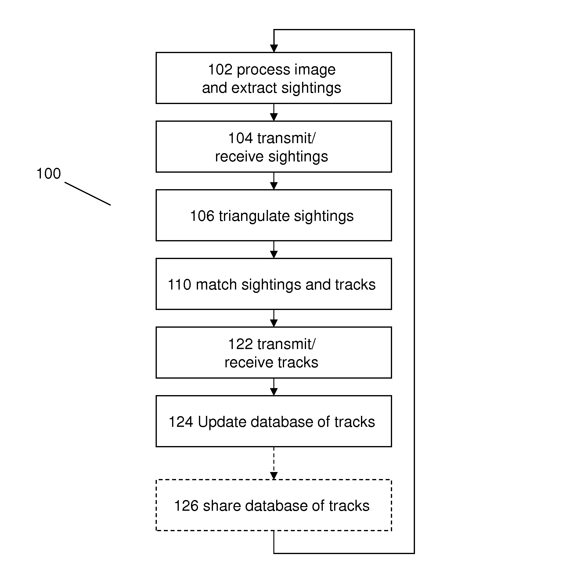
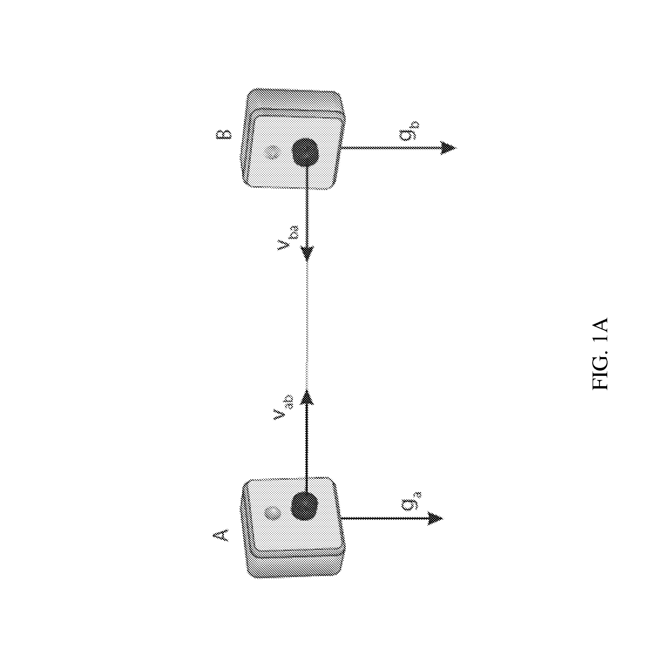
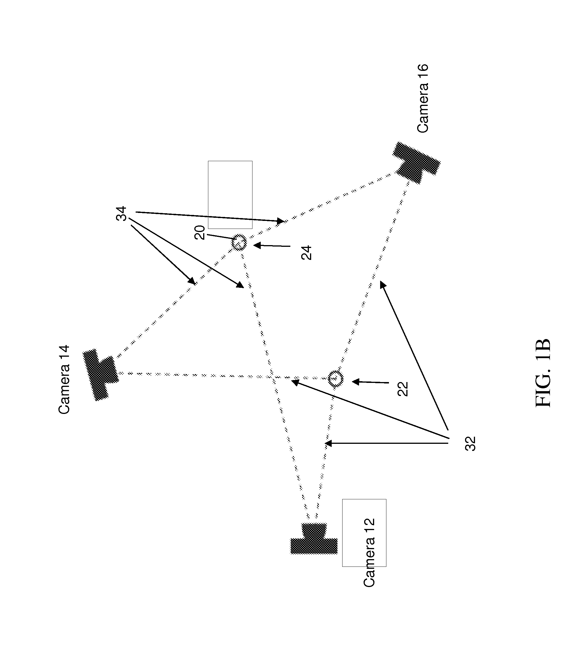
A plurality of camera devices are configured to localize one another based on visibility of each neighboring camera in an image plane. Each camera device captures images and identifies sightings of candidate targets. The camera device share information about sightings and triangulate positions of targets. Targets are matched to known tracks based on prior images, allowing targets to be tracked in a 3D environment.

Description

CROSS REFERENCE TO RELATED APPLICATIONS[0001]The present application claims priority to provisional patent applications 61 / 418,789, 61 / 418,805, and 61 / 418,799 which are incorporated by reference in their entirety.[0002]The present application relates to concurrently filed patent applications entitled “Scene Analysis Using Image and Range Data” and “Image Segmentation for Distributed Target Tracking and Scene Analysis” both of which are incorporated by reference in their entirety and filed on the same day as the present application entitled “Distributed Target Tracking Using Self Localizing Smart Camera.”TECHNOLOGY FIELD[0003]The present invention relates generally to machine vision systems and methods and specifically to object tracking and scene analysis for distributed or mobile applications.BACKGROUND[0004]The decreasing cost and increasing performance of embedded smart camera systems makes it attractive to consider applying them to a variety of surveillance and tracking applicat...

Claims


Application Information

Patent Timeline
Patent Type & Authority Patents(United States)
IPC IPC(8): H04N5/225G06K9/00G06T7/00G06T7/20H04N7/18
CPCG06K9/00771G06T7/0081G06T7/2093G06T2207/30241H04N7/181G06T7/11G06T7/292G06V20/52
Inventor TAYLOR, CAMILLO JOSE
Owner THE TRUSTEES OF THE UNIV OF PENNSYLVANIA
Learn More