
Rail vehicle emergency lighting

a technology for emergency lighting and rail vehicles, applied in emergency lighting, emergency power supply arrangements, mass transit vehicle lighting, etc., can solve the problems of inability to connect leds directly to the power supply of rail vehicles, and inacceptable dazzl

Active Publication Date: 2016-09-20
SIEMENS MOBILITY AUSTRIA GMBH
View PDF19 Cites 1 Cited by
  • Summary
  • Abstract
  • Description
  • Claims
  • Application Information

AI Technical Summary

Benefits of technology

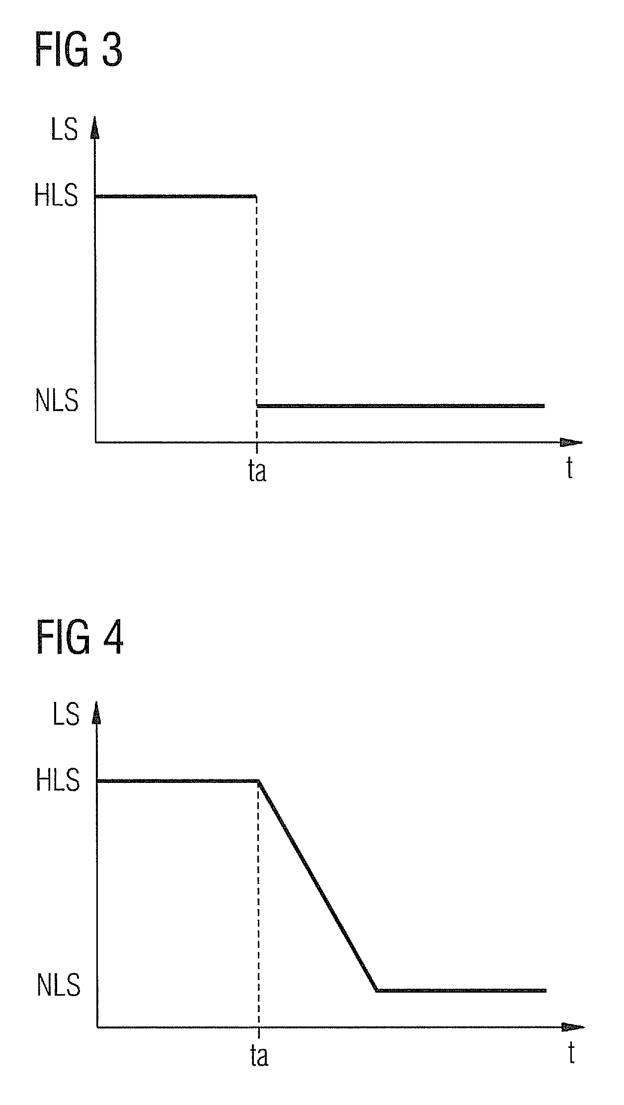
[0009]Another advantage of the invention is that the transition of the luminous intensity between main and emergency lighting can be freely designed. In particular, a delayed reduction in luminous intensity, a stepless transition or a time-phased, multi-step transition from the main lighting intensity to the emergency lighting intensity are advantageous.
[0010]As an electronic ballast which, among other things, reduces the normal rail vehicle electrical system voltage to the LED operating voltage is required for operating LEDs, the electronic circuitry required for reducing the luminous intensity can be incorporated in said ballast.
[0011]It is additionally advantageous to take the energy supply of the rail vehicle passenger compartment lighting from the emergency power supply and feed the main power supply as a control signal to the electronic ballast. This ensures reliable emergency lighting, as energy is always supplied to the entire lighting system from the constantly available emergency power supply. During normal operation (with main power supply operative) the battery of the emergency power supply is continuously charged so that said battery is not discharged by the power consumption of the main lighting.

Problems solved by technology

However, LEDs cannot be connected directly to the power supply of a rail vehicle, but require an electronic ballast which provides the required (low) operating voltage.
Nevertheless, the small size of LED light sources means high luminance which can cause dazzle.
However, the current design of emergency lighting systems in which only some of the lamps remain operative during emergency lighting mode results in unacceptable dazzle if LEDs are used.

Method used


Image

  • Rail vehicle emergency lighting
  • Rail vehicle emergency lighting
  • Rail vehicle emergency lighting

Examples


Embodiment Construction

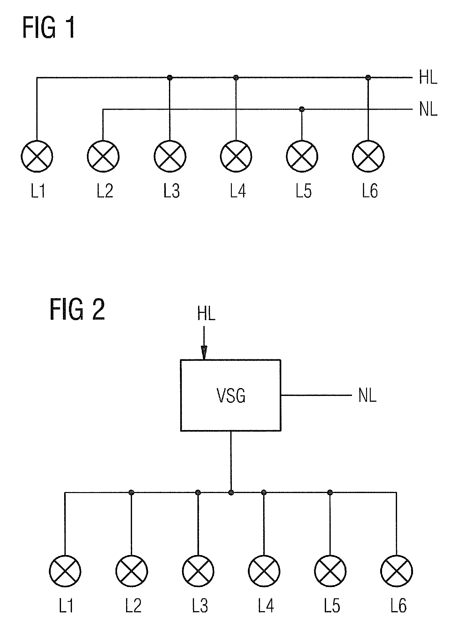
[0019]FIG. 1 shows by way of example a block schematic diagram of a rail vehicle passenger compartment lighting system. The lighting shown comprises six lamps L1 . . . L6, wherein the lamps L1, L3, L4 and L6 are supplied from the main lighting power supply HL and the lamps L2 and L5 from the emergency lighting power supply NL. If the main lighting power supply HL is unavailable, the emergency lighting comes on, in which mode the lamps L2 and L5 are in operation. Due to the reduced number of lamps or light sources in operation, dazzling may occur. Particularly when LED light sources are used, this effect is virtually unavoidable.

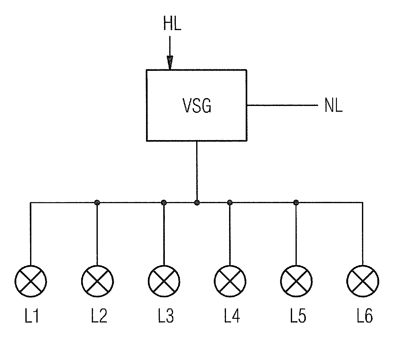
[0020]FIG. 2 shows by way of example a block schematic diagram of a rail vehicle passenger compartment lighting system with emergency lighting according to the invention. The lighting shown comprises six lamps L1 . . . L6, a ballast VSG, a main lighting power supply HL and an emergency lighting power supply NL. The ballast VSG provides the operating voltage r...


PUM


Abstract

A rail vehicle emergency lighting system for a rail vehicle includes a main lighting system with light emitting diodes. When a main lighting power supply is active, the light emitting diodes of the main lighting system are lit with a main lighting intensity. When the main lighting power supply fails, the light emitting diodes of the main lighting system are lit with an emergency lighting intensity. The emergency lighting intensity is reduced compared to the main lighting intensity.

Description

CROSS REFERENCE TO RELATED APPLICATIONS[0001]This application is the U.S. National Stage of International Application No. PCT / EP2011 / 058168 filed May 19, 2011, and claims the benefit thereof. The International Application claims the benefits of Austrian Application No. A1020 / 2010 filed Jun. 21, 2010. All of the applications are incorporated by reference herein in their entirety.TECHNICAL FIELD[0002]The invention relates to rail vehicle emergency lighting.PRIOR ART[0003]Rail passenger vehicles are equipped with electrical emergency lighting which allows the passengers to orientate themselves in the vehicle. These emergency lighting systems are usually supplied from dedicated batteries and illuminate the interior of the vehicle when an external power supply is unavailable. The emergency lighting uses individual selected lamps of the main lighting which are supplied from the emergency circuit and therefore remain operative even when the lamps supplied by the main power supply go out. I...

Claims


Application Information

Patent Timeline
Patent Type & Authority Patents(United States)
IPC IPC(8): B60Q1/14B60Q3/02H02J9/02H05B33/08B61D29/00H05B44/00
CPCB60Q3/0293B60Q3/0256B61D29/00H02J9/02H05B33/0845B60Q3/46H02J9/00H05B44/00B60Q3/80H05B45/10H02J2310/40
Inventor AMBROZ, ANTONULREICH, KLAUS
Owner SIEMENS MOBILITY AUSTRIA GMBH
Learn More