
Semiconductive roller

a semi-conductive roller and semi-conductive technology, applied in the direction of non-metal conductors, instruments, corona discharge, etc., can solve the problems of increasing hardness, affecting the performance of semi-conductive rollers, so as to reduce the resistance of semi-conductive rollers, reduce the blending proportion of electrically conductive carbon black, and prevent the contamination of the photoreceptor body

Active Publication Date: 2016-09-13
SUMITOMO RUBBER IND LTD
View PDF17 Cites 1 Cited by
  • Summary
  • Abstract
  • Description
  • Claims
  • Application Information

AI Technical Summary

Benefits of technology

The present invention relates to a method of reducing the roller resistance of a semiconductive roller used in image forming apparatuses without compromising on hardness and other mechanical properties. The method involves the combination of an ionic salt and epichlorohydrin rubber, which functions as an ion conductive agent to reduce roller resistance. This combination eliminates the need for blending electrically conductive carbon black, which can affect the hardness and other mechanical properties of the semiconductive roller. The use of the ionic salt in conjunction with epichlorohydrin rubber maintains a constant rubber composition without significant variations in toner charge amount, toner transport amount, and other electrical properties, resulting in optimal roller resistance levels. The method also prevents the formation of images with reduced image density caused by toner adhesion and suppresses variations in roller resistance due to environmental factors.

Problems solved by technology

Problematically, where the semiconductive roller is used as the developing roller, a formed image is liable to have a reduced image density.
If titanium oxide (a filler having a higher hardness) is added to the rubber composition in an amount sufficient to ensure the aforementioned function, however, the semiconductive roller is liable to have an increased hardness to cause additional problems.
More specifically, the semiconductive roller is liable to deteriorate the toner to reduce imaging durability, or liable to have a reduced nip width when being in press contact with the surface of the photoreceptor body.
Thus, the formed image is liable to have a reduced image quality.
If the imaging durability is reduced, the formed image is liable to have white streaks in its black solid portion or have fogging in its marginal portion, thereby having a reduce image quality.
Therefore, when the semiconductive roller is continuously subjected to an electric field or a higher temperature, for example, an excess amount of the ion conductive agent is liable to bleed on an outer peripheral surface of the semiconductive roller.
Problematically, the bleeding ion conductive agent is transferred to the photoreceptor body and the like to contaminate the photoreceptor body, thereby reducing the image quality of the formed image.
That is, the semiconductive roller is not allowed to have a single layer structure, thereby requiring an increased number of production steps and an increased number of materials.
Problematically, this correspondingly reduces the productivity of the semiconductive roller and increases the production costs.

Method used


Image

  • Semiconductive roller
  • Semiconductive roller
  • Semiconductive roller

Examples


example 1

Preparation of Rubber Composition

[0206]A rubber component was prepared by blending 50 parts by mass of an SBR (non-oil-extension type JSR1502 available from JSR Co., Ltd. and having a styrene content of 23.5%), 20 parts by mass of a GECO (EPION (registered trade name) 301 available from Daiso Co., Ltd. and having a molar ratio of EO / EP / AGE=73 / 23 / 4) and 30 parts by mass of a CR (SHOPRENE (registered trade name) WRT available from Showa Denko K.K.) The proportion of the SBR was 50 parts by mass and the proportion of the GECO was 20 parts by mass based on 100 parts by mass of the overall rubber component.

[0207]While 100 parts by mass of the rubber component was simply kneaded by means of a Banbury mixer, ingredients shown below in Table 1 except the crosslinking component were added to the rubber component, and then the crosslinking component was added to and further kneaded with the resulting mixture. Thus, a rubber composition was prepared.

[0208]

TABLE 1IngredientsParts by massIonic s...

example 7

[0215]A rubber composition was prepared in substantially the same manner as in Example 1, except that 0.2 parts by mass of lithium bis(trifluoromethanesulfonyl)imide (ionic salt II) based on 100 parts by mass of the overall rubber component was blended instead of the ionic salt I. Then, a semiconductive roller was produced in the same manner as in Example 1 by using the rubber composition thus prepared.

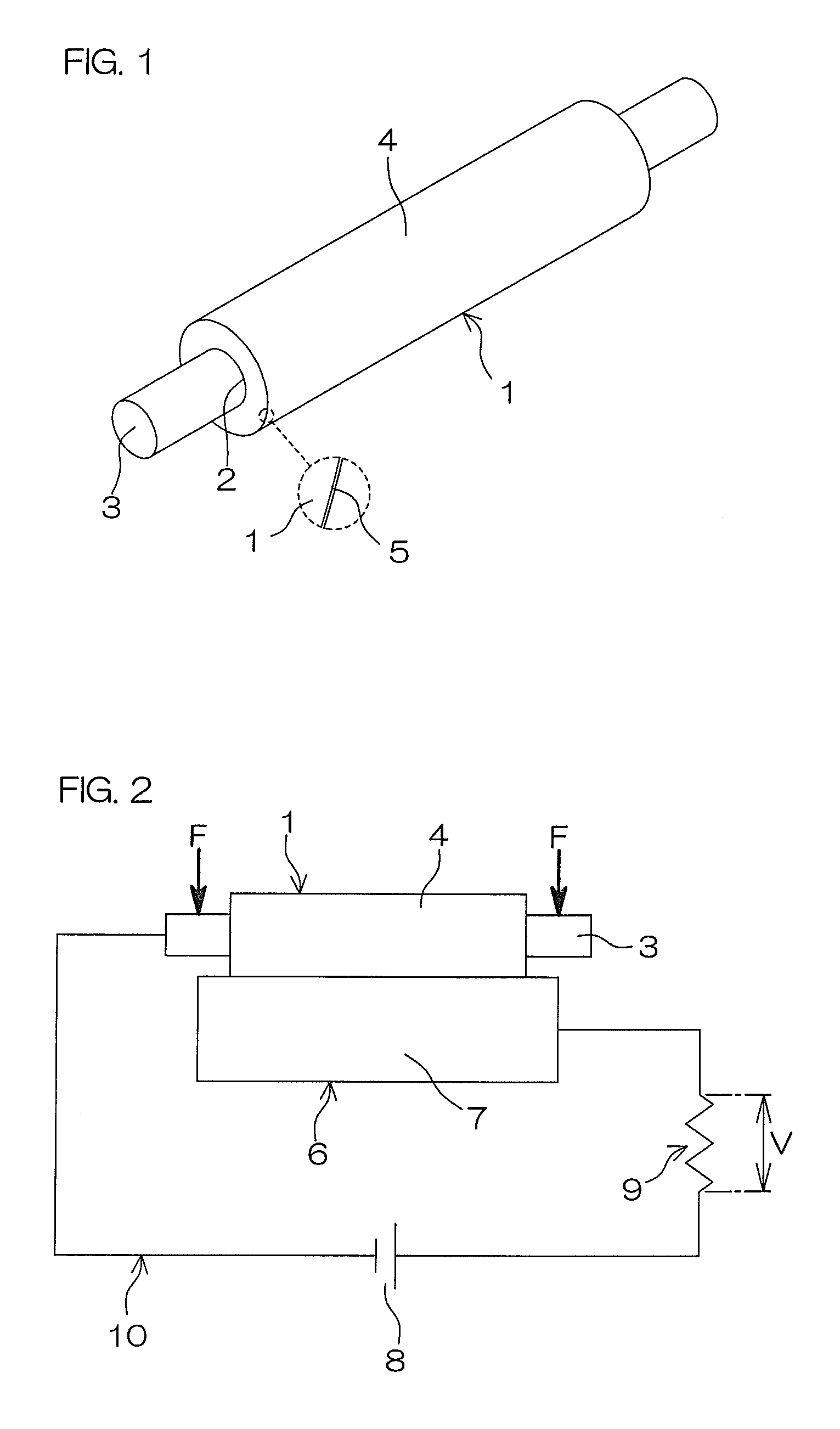
[0216]The roller resistances of each of the semiconductive rollers produced in Examples and Comparative Examples were measured in the lower temperature and lower humidity environment (LL at a temperature of 10° C. at a relative humidity of 20%), in the ordinary temperature and ordinary humidity environment (NN at a temperature of 23° C. at a relative humidity of 55%) and in the higher temperature and higher humidity environment (HH at a temperature of 30° C. at a relative humidity of 80%). In Tables 2 and 3, the roller resistances are shown in the form of log R.

[0217]Based on the meas...


PUM

PropertyMeasurementUnit
humidityaaaaaaaaaa
temperatureaaaaaaaaaa
roller resistanceaaaaaaaaaa

Abstract

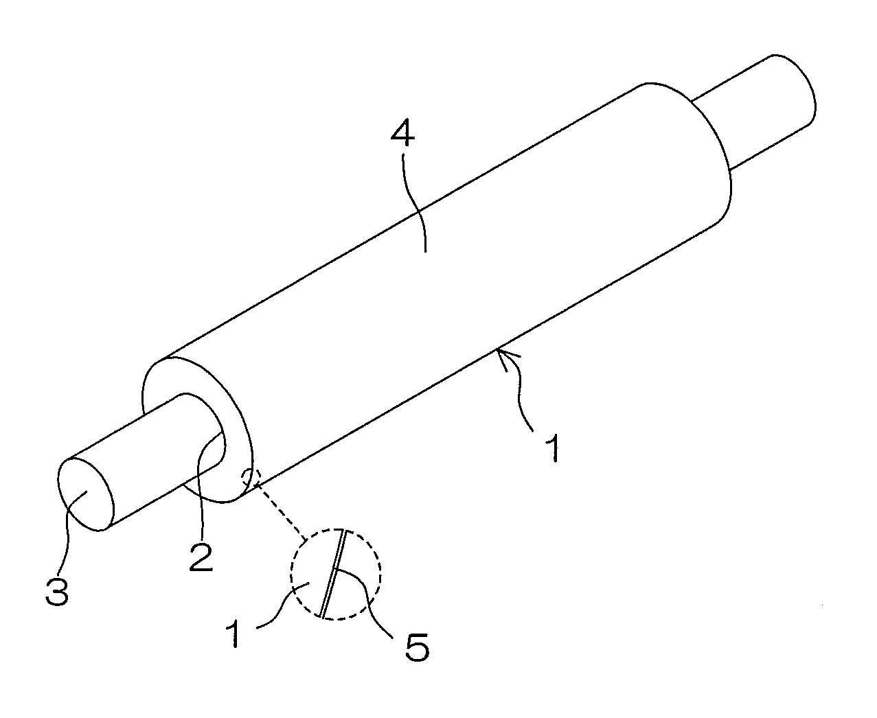
A semiconductive roller (1) according to the present invention has a nonporous single-layer structure formed from a rubber composition which includes: a rubber component including a styrene butadiene rubber and an epichlorohydrin rubber; and a salt of an anion having a fluoro group and a sulfonyl group in its molecule; the salt being present in the rubber composition in a proportion of 0.05 to 5 parts by mass based on 100 parts by mass of the overall rubber component.

Description

TECHNICAL FIELD[0001]The present invention relates to a semiconductive roller which is advantageously used particularly as a developing roller or the like in an electrophotographic image forming apparatus.BACKGROUND ART[0002]In an electrophotographic image forming apparatus such as a laser printer, an electrostatic copying machine, a plain paper facsimile machine or a printer-copier-facsimile multifunction machine, an electrostatic latent image formed on a surface of a photoreceptor body by electrically charging the photoreceptor surface and exposing the photoreceptor surface to light is developed into a toner image with a toner, and a developing roller is used for the development.[0003]There is a trend toward the use of a toner including more uniform, more spherical and smaller size toner particles or a polymeric toner. In order to impart such toner with higher electrical chargeability and efficiently develop the electrostatic latent image into the toner image without adhesion of t...

Claims


Application Information

Patent Timeline
Patent Type & Authority Patents(United States)
IPC IPC(8): G03G15/08H01B1/12G03G15/02
CPCH01B1/122G03G15/0233G03G15/0818Y10T428/31931
Inventor MIZUMOTO, YOSHIHISAMARUI, TAKASHIKURODA, KENICHI
Owner SUMITOMO RUBBER IND LTD
Learn More