Engine control device

a control device and engine technology, applied in electrical control, multi-programming arrangements, electrical control, etc., can solve the problems of significant differences in electric power consumption, insufficient processing capacity of multi-core processors, and insufficient single-core processors used in conventional engine control devices. the effect of reducing the difference between communication delay times among the cores and reducing the communication delay time itsel

Inactive Publication Date: 2016-09-13
TOYOTA JIDOSHA KK
View PDF16 Cites 0 Cited by
  • Summary
  • Abstract
  • Description
  • Claims
  • Application Information

AI Technical Summary

Benefits of technology

[0010]An object of the present invention is to enable calculation of a control target value of one or a plurality of actuators involved in engine control by a multi-core processor at a high speed and with a small amount of electric power consumption. To achieve this object, the present invention provides an engine control device that is described hereunder.
[0017]That is, according to the present invention, the engine control device uses eight cores that are associated with eight adjacent lattice points that three-dimensionally surround a current operating point to calculate a control value at each of the lattice points, and performs an interpolation calculation to calculate a control value at the current operating point based on the calculation result. Consequently, because the calculation of control values at the respective lattice points is performed in parallel by separate cores, the time required to calculate the control target value of an actuator is significantly reduced in comparison to a case in which the conventional single-core processor is used. Further, because the engine control device suspends the calculation of control values for cores other than the eight cores associated with the eight adjacent lattice points, electric power consumption can be suppressed while enabling high-speed calculation of a control target value of an actuator.
[0019]According to the preferable rule, a plurality of core group that include four adjacent cores are set. Further, four consecutive lattice points at which respective coordinates of the first and second operating conditions are identical and coordinates of the third operating condition are different are associated with the respective core groups. Furthermore, the respective core groups are arranged in an identical order as lattice points in a two-dimensional Cartesian coordinate system that takes the first operating condition and the second operating condition as axes. If the association of lattice points and cores is performed in accordance with this rule, since the control values at the respective lattice points are calculated by eight cores that are also physically close to each other, differences in communication delay times between cores can be reduced. By reducing differences in the communication delay times, it is possible to calculate control values with a high level of efficiency in the processor overall.
[0020]Further, when the association of lattice points and cores is performed according to the above described rule, it is more preferable to interchange lattice points that the respective cores are responsible for in sequential order within the core group. It is thereby possible to prevent deterioration of cores that is cause by a calculation load being concentrated at some cores. The interchange of lattice points that the respective cores are responsible for may be performed, for example, after every predetermined amount of driving trips.
[0022]First, the respective control value calculation cores determine whether or not a lattice point associated therewith is a representative lattice point among the eight adjacent lattice points that define the operation space to which the current operating point belongs. Hereunder, a core corresponding to a representative lattice point is referred to as a “representative core”. In a case where the respective control value calculation cores determine that the relevant control value calculation core is not a representative core, the relevant control value calculation core sends a control value at a lattice point that is associated therewith to another core that is the representative core. On the other hand, if the relevant core is the representative core, the relevant core receives control values calculated at the respective cores with which the other lattice points that define the operation space to which the current operating point belongs are associated from the respective cores. The relevant core then calculates a control value at the current operating point by performing an interpolation calculation by means of the interpolation calculation program based on the control values at the eight adjacent lattice points that define the operation space to which the current operating point belongs. By programming the respective cores to perform the above described processing, not only can a difference between communication delay times among the cores be reduced, but the communication delay time itself can also be decreased.

Problems solved by technology

Consequently, there has been a concern that the processing capacity of single-core processors used in the conventional engine control devices will soon be insufficient for processing such increasing calculation loads.
However, the processing capacity of a multi-core processor is not simply determined by the number of cores.
For example, although it is possible to distribute tasks to a plurality of cores and perform processing in parallel when using a multi-core processor, significant differences in the overall processing capacity arise depending on the parallelization technique, and this results in significant differences in the electric power consumption also.

Method used


Image

  • Engine control device
  • Engine control device
  • Engine control device

Examples


Embodiment Construction

[0036]An engine control device according to an embodiment of the present invention is described hereunder with reference to the accompanying drawings.

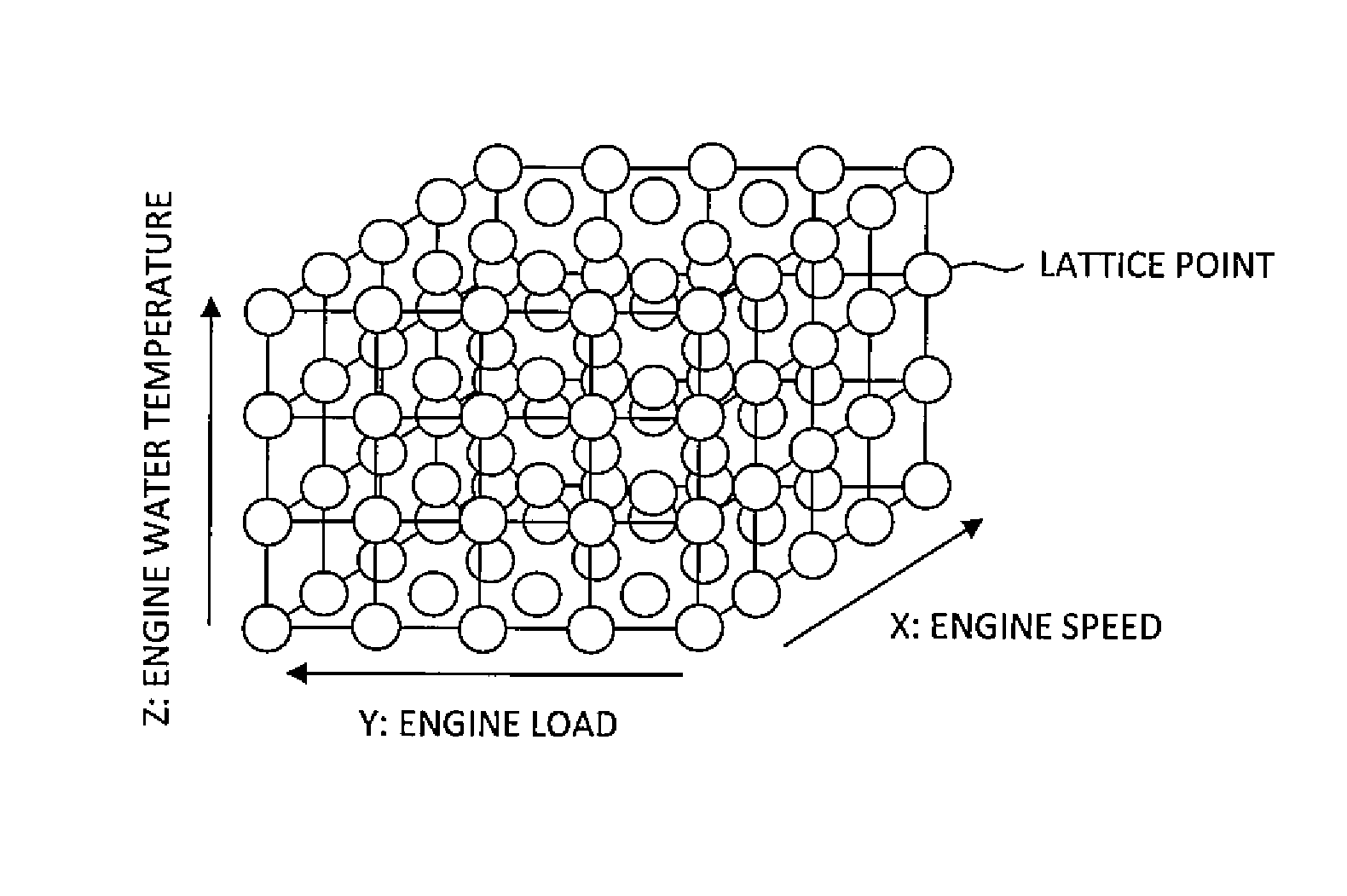
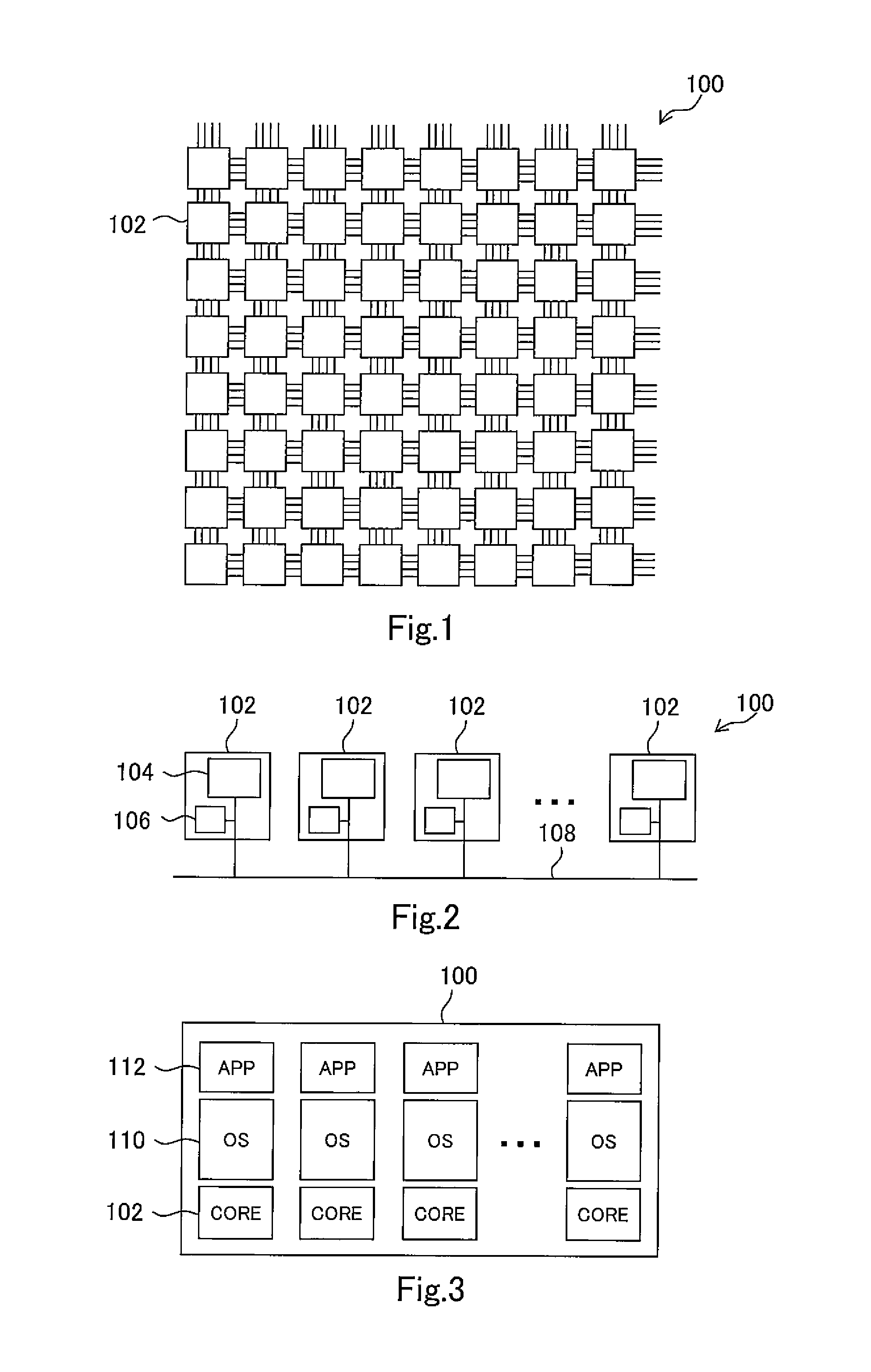
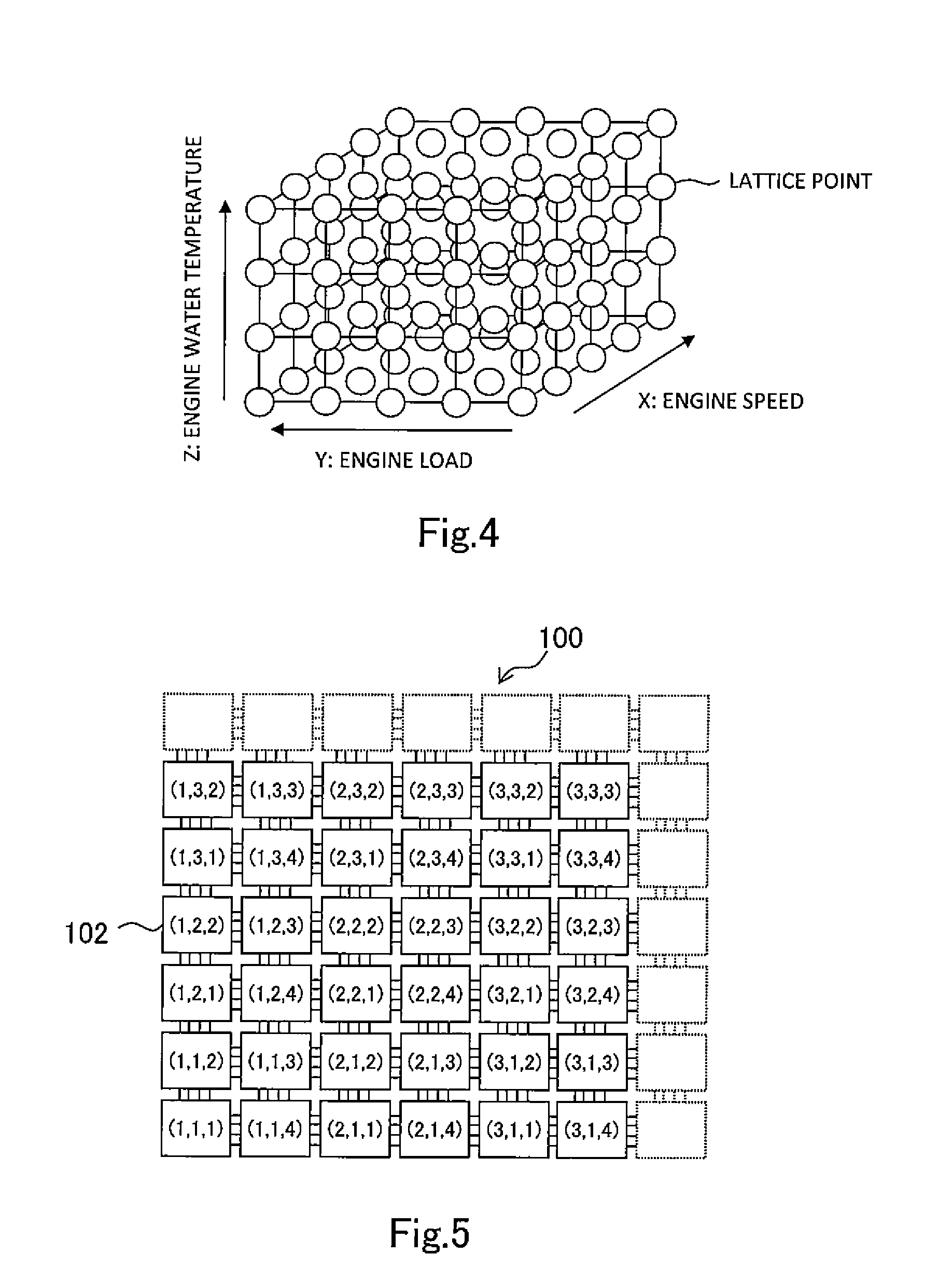
[0037]An engine control device to which the present invention is applied is a device that calculates control target values of actuators involved in engine control using a multi-core processor. In the present invention, there is no limitation with respect to the kind or structure of an automobile engine controlled by the engine control device, and there is also no limitation with respect to the kind or number of actuators. For example, the engine control device of the present embodiment may be a control device for a gasoline engine. In such case, the engine control device calculates control target values of actuators such as a throttle, an ignition device, an injector, an EGR valve, a variable valve mechanism and a waste gate valve. The engine control device of the present embodiment may also be a control device for a diesel engine. In ...


PUM


Abstract

Multiple lattice points arranged in a three-dimensional Cartesian coordinate system that takes first, second and third operating conditions as axes are associated with cores arranged in a lattice shape. A program for calculating a control value at the associated lattice points is allocated to the cores. Each core with which a lattice point is associated is configured so that, in a case where an operation space on the three-dimensional Cartesian coordinate system to which a current operating point belongs is a space defined by eight adjacent lattice points including a lattice point associated with the relevant core, the relevant core calculates a control value at the lattice point associated therewith by means of the calculation program and sends the control value to an interpolation calculation core. Further, if the operation space is not defined by the eight adjacent lattice points, the relevant core suspends calculation of the control value.

Description

CROSS-REFERENCE TO RELATED APPLICATIONS[0001]This is a national phase application based on the PCT International Patent Application No. PCT / JP2011 / 078691 filed Dec. 12, 2011, the entire contents of which are incorporated herein by reference.TECHNICAL FIELD[0002]The present invention relates to a control device for an automobile engine that determines a control target value of an actuator based on a plurality of operating conditions, and more particularly relates to an engine control device that calculates a control target value of an actuator using a multi-core processor having a plurality of cores.BACKGROUND ART[0003]In recent years, the use of arithmetic devices in which a plurality of CPU cores are mounted on one semiconductor chip, that is, multi-core processors, has been proposed in various fields. The use of multi-core processors is also being studied in the field of automobile engine control, as disclosed, for example, in Japanese Patent Laid-Open No. 2008-269487. The technol...

Claims


Application Information

Patent Timeline
Patent Type & Authority Patents(United States)
IPC IPC(8): G06F19/00G06F9/46G06G7/70G05B15/02G06F12/08F02D41/24F02D41/26
CPCG05B15/02F02D41/2416F02D41/26G06F9/46G06F12/084Y02T10/46Y02T10/40
Inventor WATANABE, SATORU
Owner TOYOTA JIDOSHA KK
Why Eureka
Try Eureka