
Optical device, in particular for a motor vehicle

a technology of optical devices and motor vehicles, applied in the direction of lighting support devices, fixed installations, lighting and heating apparatus, etc., can solve the problems of light curved, light insufficient brightness of organic light-emitting diodes of present-day technology, etc., and achieve the effect of increasing the emitted luminous intensity

Active Publication Date: 2016-09-13
VALEO VISION SA
View PDF24 Cites 4 Cited by
  • Summary
  • Abstract
  • Description
  • Claims
  • Application Information

AI Technical Summary

Benefits of technology

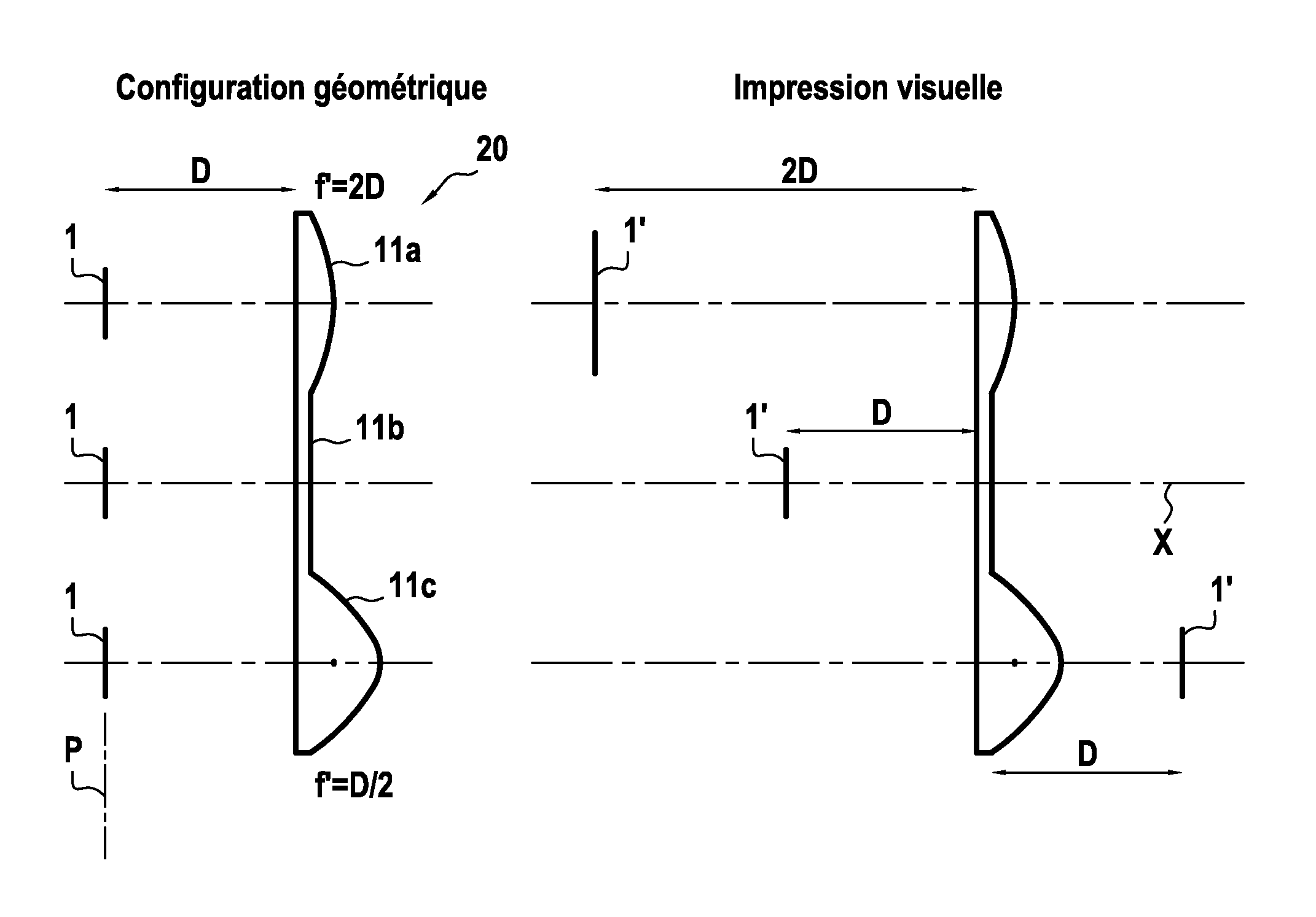
[0020]The invention enables certain effects, notably of depth, to be obtained by adjusting the relative position of the source and the lens, the size of the source and the focal length of the lens.
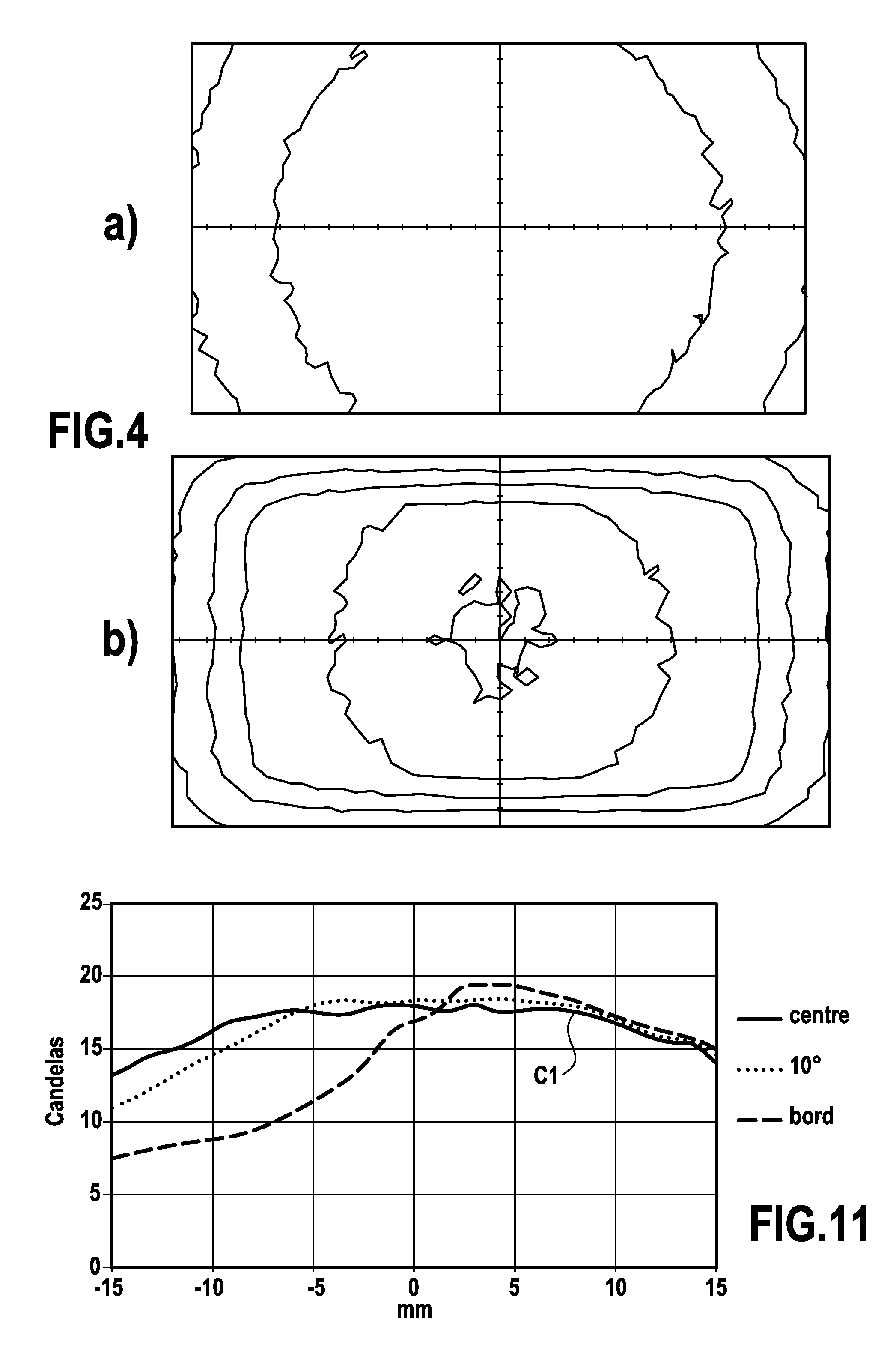
[0021]The invention makes it possible in particular to increase the emitted luminous intensity and / or to create an effect of depth.
[0030]This enables a simpler design of device because fewer parts are necessary.
[0034]In one embodiment of the invention the device is, notably the lenses are, arranged to form images corresponding to the object areas, which images are offset relative to each other along the optical axis, notably to create an effect of depth.
[0042]in association with the lens, efficiency is improved, i.e. the shape of the beam and the on-axis luminous intensity are improved,
[0048]This enables the relatively low brightness to be alleviated. Thus, to obtain equivalent photometry, cost may be reduced by using sources of smaller size than when an OLED is used on its own.

Problems solved by technology

The brightness of an organic light-emitting diode of the present-day technology may not be sufficient to provide some signaling functions (such as “side light”, “brake light” and “high-level brake light” signaling functions).
Although the first characteristic is favorable (because homogeneous light is appreciated by motor vehicle manufacturers, for example), the other two characteristics may be problematic in that a light is often curved.

Method used


Image

  • Optical device, in particular for a motor vehicle
  • Optical device, in particular for a motor vehicle
  • Optical device, in particular for a motor vehicle

Examples


Embodiment Construction

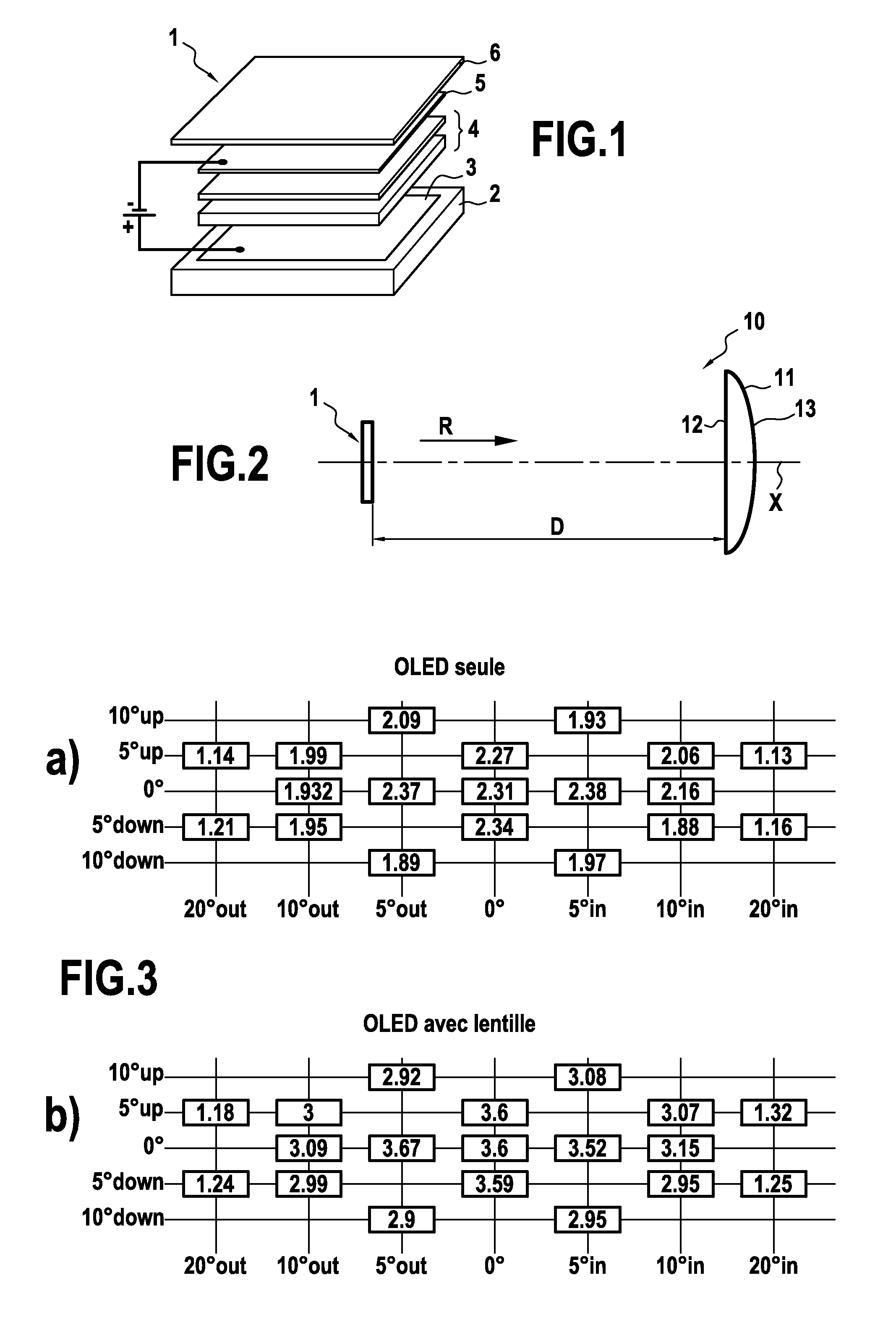
[0065]There has been represented in FIG. 1 an organic light-emitting diode adapted to form a surface-emitting light source 1 as that term is used in the context of the present invention.

[0066]This surface-emitting light source 1 includes:[0067]a substrate 2, for example of glass,[0068]an anode 3 deposited on this substrate 2,[0069]a plurality of organic layers 4 within which light can be generated,[0070]a cathode 5, for example in aluminum,[0071]an encapsulation layer 6.

[0072]These various elements are superposed, forming a sandwich structure with a thickness of approximately 200 nm, for example.

[0073]Light is generated within the organic layers 4 when an electric current flows between the anode 3 and the cathode 5 through the organic layers 4.

[0074]Of course, the surface-emitting light source 1 in the sense of the present invention may employ a technology other than the OLED technology.

[0075]There has been represented in FIG. 2 a device 10 conforming to one embodiment of the invent...


PUM


Abstract

An optical device for automobile vehicles, notably a signalling and / or lighting device. The device comprises at least one surface-emitting light source, at least one lens, notably distant from the surface-emitting light source, disposed at least partially on the path of the light (R) emitted by the surface-emitting light source so as to produce an image of an object area of the surface-emitting light source.

Description

CROSS-REFERENCE TO RELATED APPLICATIONS[0001]This application claims priority to PCT Application PCT / EP2011 / 050849 filed Jan. 21, 2011, and also to French Application No. 1050489 filed Jan. 26, 2010, which applications are incorporated herein by reference and made a part hereof.BACKGROUND OF THE INVENTION[0002]1. Field of the Invention[0003]The invention concerns an optical device, notably for a motor vehicle, such as a lighting and / or signaling device having in particular a photometric function useful for circulation of the vehicle on roads, enabling the vehicle to be seen by other vehicles or the driver of the vehicle to see outside.[0004]2. Description of the Related Art[0005]It is known, in particular from the document DE 10 2007 018 985, which document is incorporated herein by reference and made a part hereof, to use surface-emitting light sources, in particular an organic light-emitting diode, as the light source of a motor vehicle signaling device. An organic light-emitting ...

Claims


Application Information

Patent Timeline
Patent Type & Authority Patents(United States)
IPC IPC(8): F21V21/00F21S8/10F21Y105/00
CPCF21S48/215F21S48/2212F21S48/1163F21S48/125F21Y2105/00F21Y2115/15F21S41/155F21S41/25F21S43/14F21S43/26
Inventor GODBILLON, VINCENT
Owner VALEO VISION SA
Learn More