
Offset voltage eliminating circuit structure for protection mechanism of dimmer

a technology of protection mechanism and circuit structure, which is applied in the direction of electric variable regulation, process and machine control, instruments, etc., can solve the problems of physical characteristics, current that flows through the current-limiting resistor will inevitably create a voltage drop, and achieve the effect of eliminating circuit structur

Active Publication Date: 2016-09-06
YUJING ENERGY TECH CO LTD
View PDF5 Cites 0 Cited by
  • Summary
  • Abstract
  • Description
  • Claims
  • Application Information

AI Technical Summary

Benefits of technology

The present invention provides an offset voltage eliminating circuit structure for a protection mechanism of a dimmer. This structure includes a subtractor that eliminates the voltage offset created by an additional current-limiting resistor used for circuit protection to obtain the correct dimming signal voltage. The main circuits of the structure can be packaged into a single integrated circuit, allowing more freedom and independence when being used, and reducing the overall size and improving space utilization.

Problems solved by technology

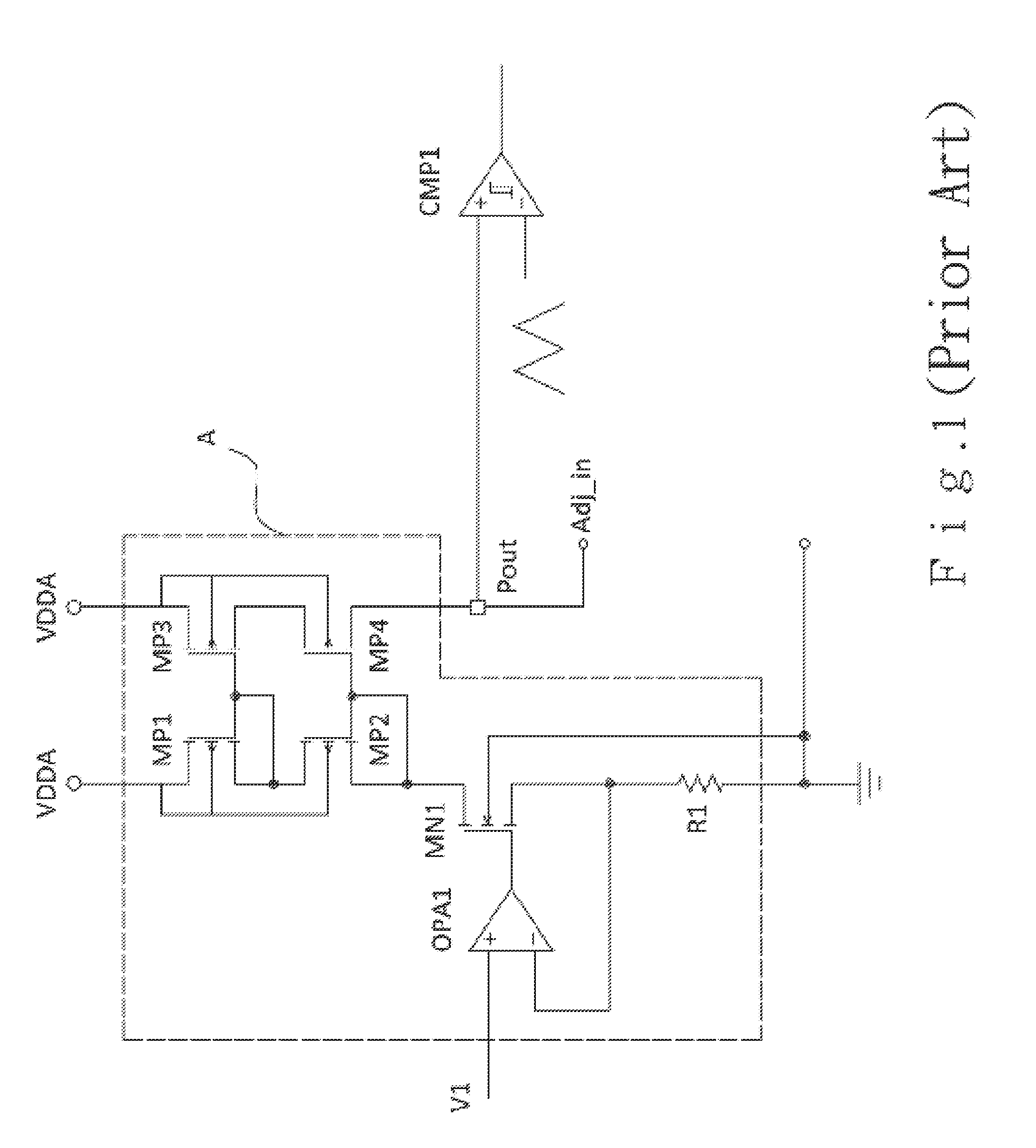
However, there are considerable differences in the physical characteristics between LEDs and traditional light elements, such that a dimmer circuit suitable for a traditional light element may not be used directly to control the brightness of a LED.
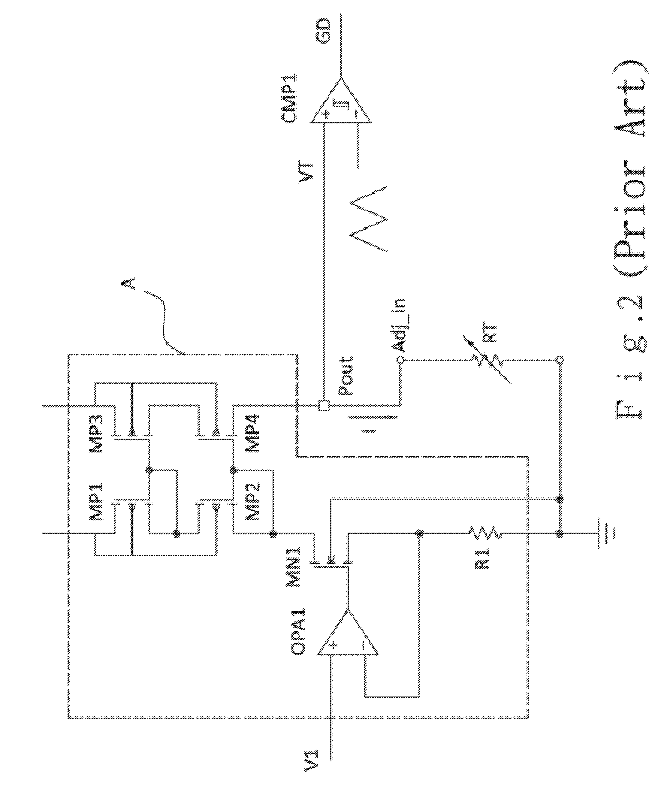
Therefore, under normal use (this is especially the case for resistive dimmers, in which the control voltage is formed across a variable resistor RT by outputting a current from the constant current source A), any current that flows through the current-limiting resistor will inevitably create a voltage drop.

Method used


Image

  • Offset voltage eliminating circuit structure for protection mechanism of dimmer
  • Offset voltage eliminating circuit structure for protection mechanism of dimmer
  • Offset voltage eliminating circuit structure for protection mechanism of dimmer

Examples


Embodiment Construction

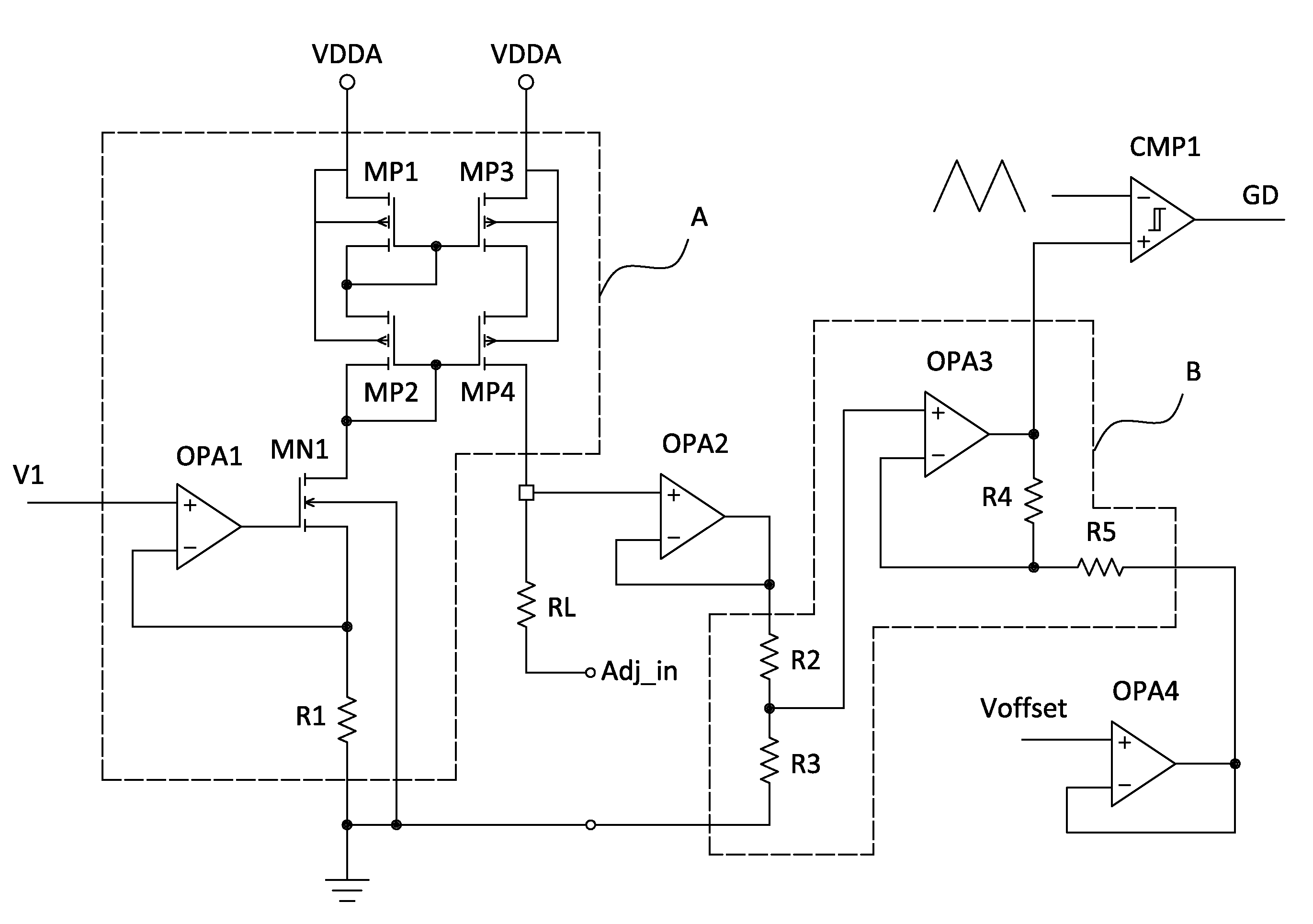
[0024]Referring to FIG. 5, a circuit structure in accordance with the present invention mainly includes: a constant current source A, a subtractor B and a hysteresis comparator CMP1. The constant current source A is formed of a cascaded current mirror circuit consisting of symmetric P-type transistors MP1, MP2, MP3 and MP4 and an N-type transistor MN1, a first operational amplifier OPA1 and a first resistor R1. A voltage V1 can be input into the non-inverting input of the first operational amplifier OPA1. The inverting input of the first operational amplifier OPA1 is connected to the gate of the N-type transistor MN1 and grounded via the first resistor R1. The source of the P-type transistor MP4 is connected to an output Pout. The output Pout is also connected to a dimming signal input ADJ_in.

[0025]The subtractor B is formed of a third operational amplifier OPA3 and second, third, fourth and fifth resistors R2, R3, R4 and R5 that have the same resistances. The second and the third r...


PUM


Abstract

An offset voltage eliminating circuit structure for a protection mechanism of a dimmer is described. The circuit includes a constant current source, a subtractor and a hysteresis comparator. The constant current source is used for outputting a stable current, the output of the constant current source is connected with a dimming signal input through a current-limiting resistor, and the dimming signal input is connected with an output of an external traditional dimmer.

Description

BACKGROUND OF THE INVENTION[0001]1. Field of the Invention[0002]The invention relates to an offset voltage eliminating circuit structure for a protection mechanism of a dimmer, and more particularly, to a circuit that provides a current output when connected to an external resistive dimmer and eliminates the offset voltage created by an external limiting resistor used for circuit protection.[0003]2. Description of the Prior Art[0004]LEDs are widely used in various lighting conditions due to their characteristics such as low energy consumption and long life. However, there are considerable differences in the physical characteristics between LEDs and traditional light elements, such that a dimmer circuit suitable for a traditional light element may not be used directly to control the brightness of a LED. As such, one possible approach is to connect a converting circuit between the LED and the traditional dimmer circuit in order to turn the control mechanism of the traditional dimmer c...

Claims


Application Information

Patent Timeline
Patent Type & Authority Patents(United States)
IPC IPC(8): H05B33/08H02M3/155H05B44/00
CPCH05B33/0809H02M3/155H05B33/0845H05B45/10Y02B20/30H05B45/397
Inventor YANG, SEN-TAI
Owner YUJING ENERGY TECH CO LTD
Learn More