Hinge assembly for supporting a fan on a roof

a fan and housing technology, applied in lighting and heating apparatus, ventilation systems, heating types, etc., can solve the problems of affecting the air flow, affecting the operation of the fan, so as to achieve the effect of convenient cleaning procedur

Active Publication Date: 2016-09-06
OMNI CONTAINMENT SYST
View PDF8 Cites 6 Cited by
  • Summary
  • Abstract
  • Description
  • Claims
  • Application Information

AI Technical Summary

Benefits of technology

[0017]Among the many objectives of this invention is the provision of a buttressed hinge assembly, which supports a fan on a roof, while providing for an easy cleaning procedure for both the fan and the vent on the roof.
[0018]A further objective of this invention is the provision of a buttressed hinge assembly, which greatly simplifies cleaning of a vent for a restaurant.
[0019]Yet a further objective of this invention is the provision of a buttressed hinge assembly, which greatly simplifies cleaning of a fan.

Problems solved by technology

This power requirement leads to large and heavy fans.
By moving air through the vent, both the vent and the fan will become contaminated.
When a fan or a vent is contaminated, air flow is compromised.
This causes a great deal of stress in the affected area, which leads to equipment breakdown and damage to the fan housing.
These hinge systems are operable only with a small percentage of the fans in use today and cannot be modified to adapt to other fans.
As the fan size increases, movement thereof becomes even more difficult, which further complicates the cleaning process.
The effectiveness of these systems, and in many cases the possibility of installing them at all, is limited by a number of factors including the weight and dimensions of the fan, low grade material and components, which leads to a lack of durability, and a lack of versatility, meaning an inability to adapt to a variety of different situations that may be involved with hinge installation on any given fan.
After a period of use, this vent and the fan become contaminated with that grease.
This basically flammable residue is at least a fire hazard, or worse.
Such residue can also attract undesirable microbes and illness causing bacteria.
The closeness of such contamination to a food source is a clear danger to those food consumers and food handlers, who are at the restaurant.
While the fan is necessary for the vent to work, the fan causes many problems, when the time to clean the vent and the fan comes.
Still, there are many problems with such a cleaning process and the related device.
A first problem is that the fan must be moved, in order to clean the vent.
A properly mounted fan is difficult to move and reinstall properly.
The hinges of the prior art weaken the mounting of the fan, especially if the fan is easily movable.
If the hinge is strong enough to firmly support the fan, the fan is not easily moved, and access to the vent becomes more complicated.
The hinge kits of the prior art are constructed from thin gauge steel and inadequate hardware.
This leads to premature equipment failure and can cause the fan to overextend or even fall off of the duct.
Most hinges cannot support the weight of heavier fans.
These components are the source of a number of problems.
First, those holding devices, especially the chains, have a tendency to fail.
When they do fail, the fan can fall backward violently, damaging the fan and posing an injury risk.
They must be precisely measured and installed, adding a time-consuming factor to the installation process.
Also they are a major inconvenience and obstruction to workers that clean and service the fan.
Yet obtaining adjustability can interfere with both strength and access to both the fan and the vent.
Emphasizing one desired feature can interfere with the other.

Method used


Image

  • Hinge assembly for supporting a fan on a roof
  • Hinge assembly for supporting a fan on a roof
  • Hinge assembly for supporting a fan on a roof

Examples


Embodiment Construction

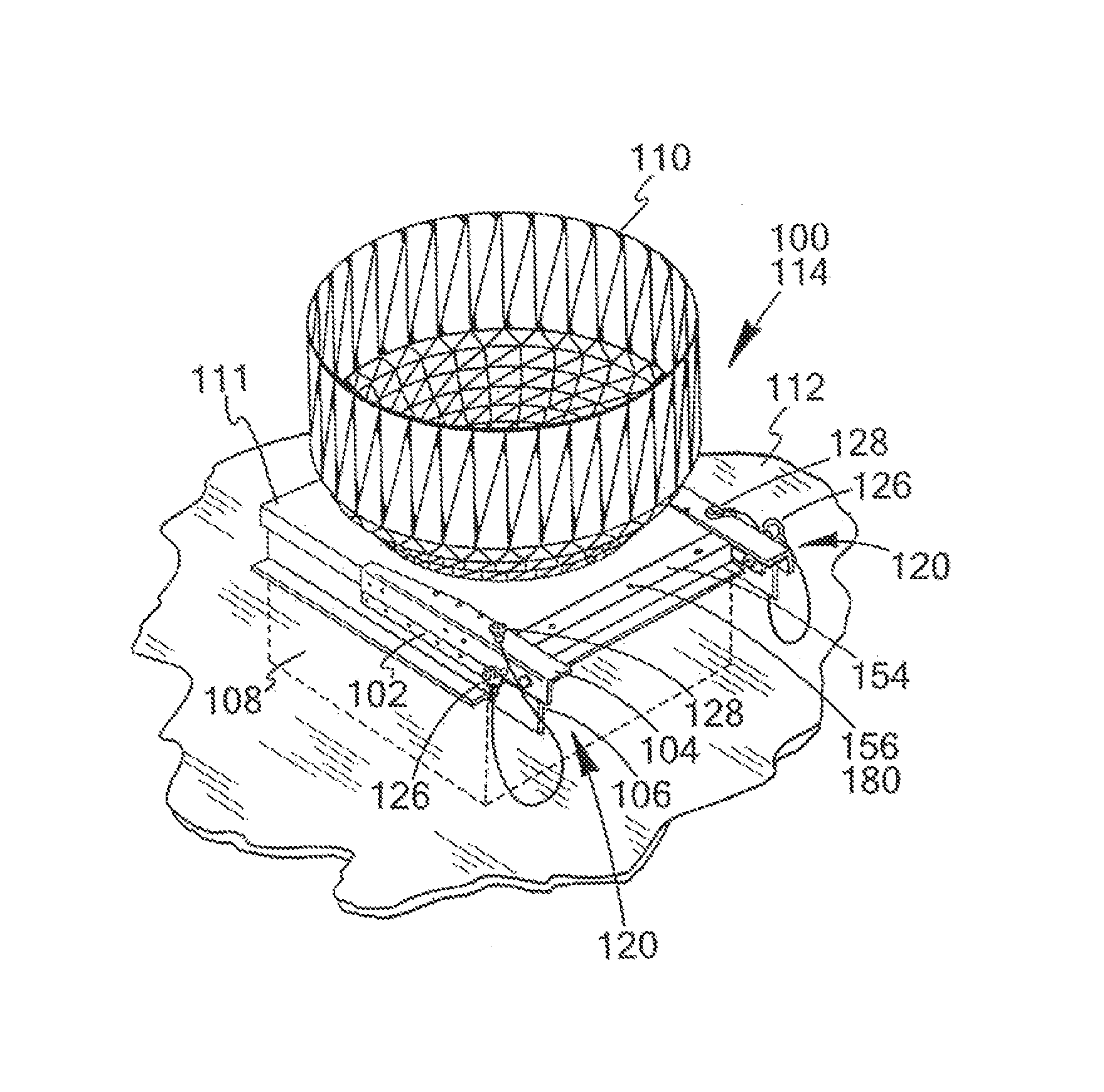
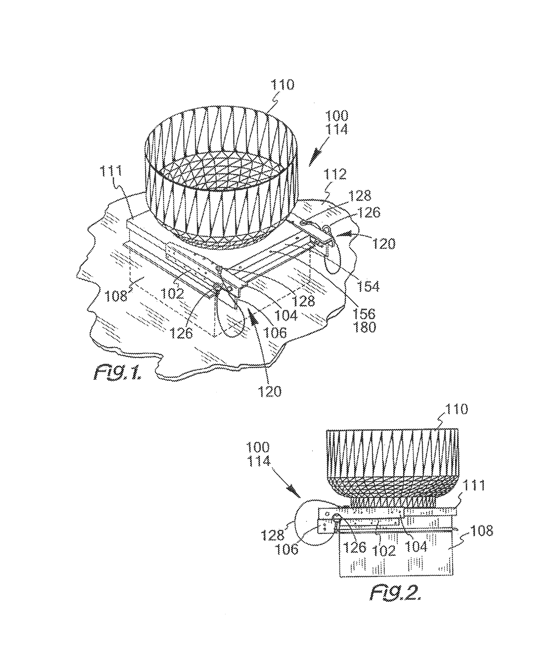
[0086]In accordance with the present invention, the buttressed hinge assembly is depicted. The buttressed hinge assembly consists of a mounting support bar and a fan support bar connected together through a hinge. The fan support bar is also connected to the fan in order to hold the fan in a position and within a relationship to the roof duct. The hinge allows that fan to be securely held in multiple positions to provide easier access to the fan and duct walls during cleaning, while at the same providing a strong support for the fan as it works in a proper position on the roof.

[0087]This hinge is fastened and clamped over a much larger area of the fan base and duct. This causes stress to be more evenly distributed, which protects the fan housing and prolongs the life of the hinge system. This hinge can be installed on most fans and has a number of adjustment capabilities that allow it to be installed on almost all other fan duct combinations.

[0088]This hinge is preferably made of ru...


PUM


Abstract

A hinge assembly or a flexible hinge assembly adjusts to fit a vent on a wall or a roof in order to hold a fan thereon, which fan is especially suitable for a restaurant roof or wall. The hinge assembly attaches to a roof or wall vent to hold the fan in a proper position, yet permits the fan to be easily moved for cleaning of vent and the fan.

Description

CROSS REFERENCE TO RELATED APPLICATIONS[0001]This application is a continuation of U.S. application Ser. No. 12 / 931,311 filed Jan. 28, 2011, which is a continuation in part of U.S. application Ser. No. 12 / 657,918 filed Jan. 29, 2010, which is a continuation in part of U.S. application Ser. No. 11 / 551,285 filed Oct. 20, 2006. All of which are incorporated by reference in their entirety.FIELD OF THE INVENTION[0002]This invention relates to a hinge assembly for supporting a fan on a roof and, more particularly, to a buttressed or flexible hinge assembly, which supports the fan on the roof, while providing for an easy cleaning procedure for both the fan and the vent on the roof.BACKGROUND OF THE INVENTION[0003]Ventilation is very important in a building. To that end, at least one fan may be installed in order to assist air circulation. In a large building, the fan is required to be quite powerful. This power requirement leads to large and heavy fans. Typically, such a fan is mounted ove...

Claims


Application Information

Patent Timeline
Patent Type & Authority Patents(United States)
IPC IPC(8): F24F7/06F24F7/02F04D29/44F24F13/32F23L17/00
CPCF24F7/025F24F7/02F24F13/32
Inventor CHWALA, KEVIN R.
Owner OMNI CONTAINMENT SYST
Why Eureka
Try Eureka