Combined rocker arm apparatus for actuating auxiliary valve of engine

a technology of auxiliary valve and rocker arm, which is applied in the mechanical field, can solve the problems of increasing height, weight and cost of the engine, and the inability of existing dedicated rocker arm brake devices to apply to the engine, so as to improve engine braking performance, increase the size and weight of the engine, and achieve positive and obvious effects

Active Publication Date: 2016-09-06
SHANGHAI UNIVERSOON AUTOPARTS CO LTD
View PDF19 Cites 5 Cited by
  • Summary
  • Abstract
  • Description
  • Claims
  • Application Information

AI Technical Summary

Benefits of technology

[0013]An object of the present application is to provide a combined rocker arm device for producing an auxiliary engine valve event, so as to solve the technical problem in the prior art that the dedicated rocker arm brake system cannot be applied to the engines with the valve bridge being parallel to the rocker arm and to address the technical problems of increased engine height, weight and cost of a conventional engine brake device.
[0024]The present application has positive and obvious effects over the prior art. In the present application, less or no height, size and weight of the engine need to be increased, the application scope of the dedicated cam or the dedicated rocker arm brake device is enlarged, the engine braking performance is improved, and the affect of the engine braking operation on the engine ignition operation is reduced.

Problems solved by technology

This arrangement may additionally increase height, weight, and cost to the engine.
However, the existing dedicated rocker arm brake device cannot be applied to the engines with the valve bridge being parallel or almost parallel to the rocker arm.

Method used


Image

  • Combined rocker arm apparatus for actuating auxiliary valve of engine
  • Combined rocker arm apparatus for actuating auxiliary valve of engine
  • Combined rocker arm apparatus for actuating auxiliary valve of engine

Examples


embodiment

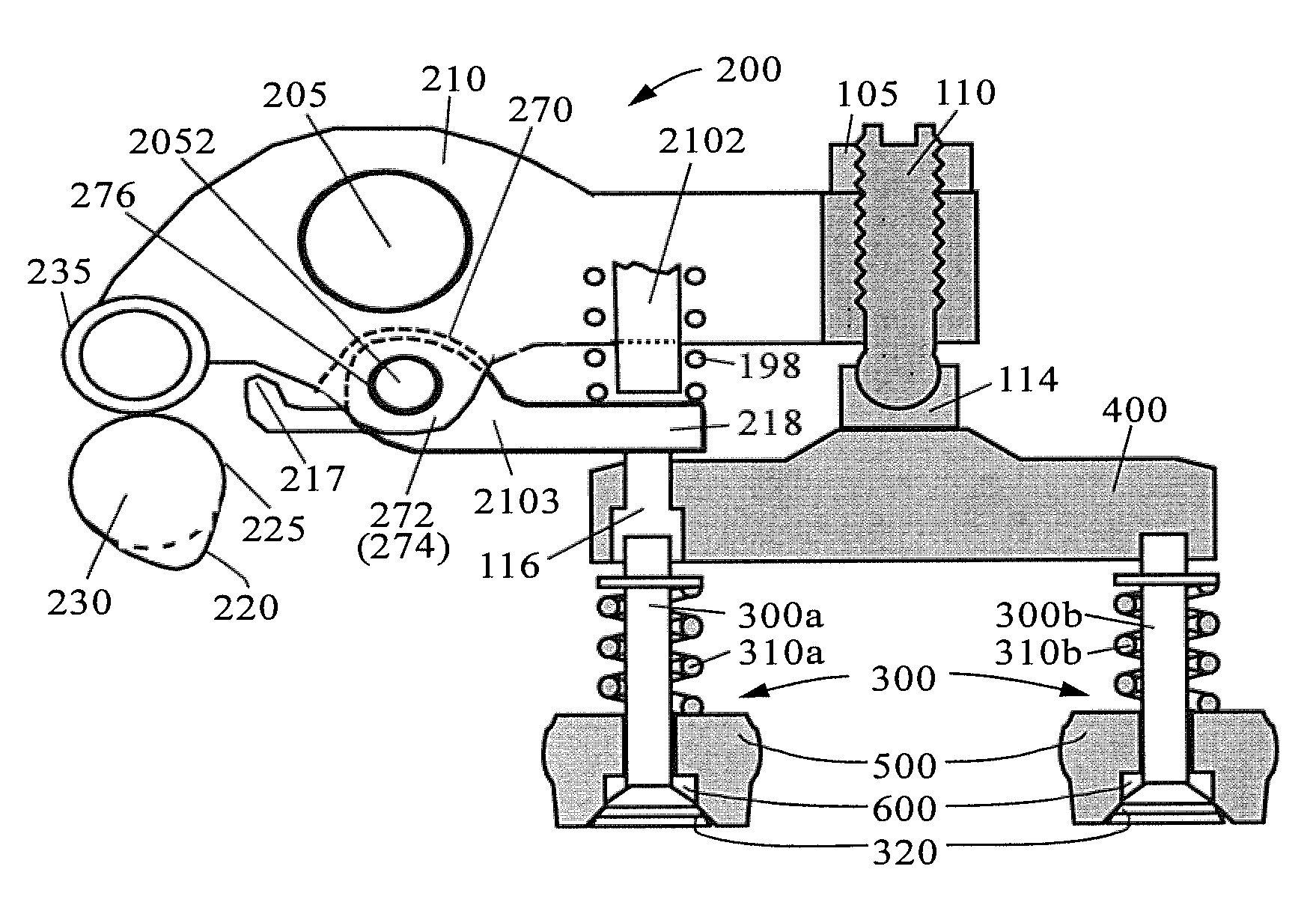
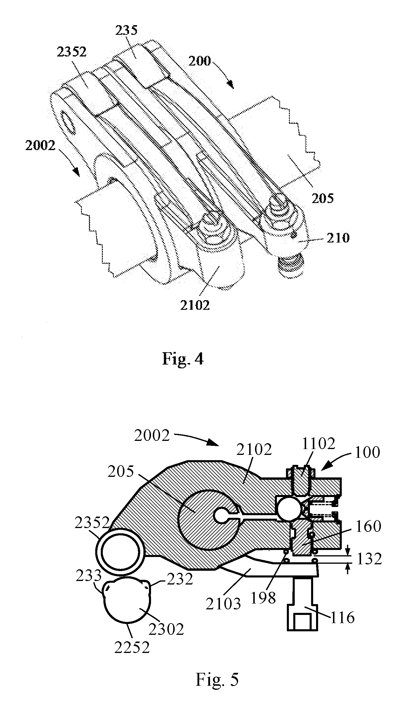
[0031]FIG. 1 is a schematic diagram illustrating the positional relationship among a transition rocker arm 2103, a conventional rocker arm 210 and a valve actuator 200 of a combined rocker arm device for an auxiliary engine valve event according to an embodiment of the present application. The auxiliary valve event generated by the combined rocker arm device of the present embodiment is an exhaust valve event for engine braking. The conventional engine exhaust valve event is generated by the engine exhaust valve actuator 200. The auxiliary exhaust valve event for engine braking is generated by an auxiliary actuator 2002. The auxiliary actuator 2002 includes an auxiliary rocker arm (shown as a brake rocker arm) 2102 and an auxiliary cam (shown as a brake cam 2302 shown in FIG. 5). It should be noted that the embodiment should not be regarded as limitation on the scope of the claims, but rather as exemplification of the present application.

[0032]The exhaust valve actuator 200 has many...


PUM


Abstract

A combined rocker arm apparatus for actuating auxiliary valve of engine, comprises an auxiliary actuator, a main rocker arm and a secondary rocker arm. The auxiliary actuator comprises an auxiliary rocker arm and an auxiliary cam. The auxiliary rocker arm and the main rocker arm are mounted on the rocker arm shaft in parallel. The auxiliary rocker arm is connected to the auxiliary cam at one end and adjacent to the secondary rocker arm at the other end. The auxiliary rocker arm includes a drive mechanism which provided with a piston. In the non-operation mode of the drive mechanism, the piston is drawn back, then the auxiliary rocker arm is disconnected with the secondary rocker arm; in the operation mode of the drive mechanism, the piston is pushed out, then the auxiliary rocker arm is connected with the secondary rocker arm.

Description

CROSS-REFERENCE TO RELATED APPLICATIONS[0001]The present application is a national filing in the U.S. Patent & Trademark Office of International Patent Application PCT / CN2011 / 000775 filed May 3, 2011. and claims priority of Chinese Patent Application NO. 201010604203.3 filed Dec. 21, 2010.FIELD OF THE INVENTION[0002]The present application relates to the mechanical field, specifically to the valve actuation technology for vehicle engines, particularly to a combined rocker arm device for an auxiliary engine valve event.BACKGROUND OF THE INVENTION[0003]In the prior art, the method of conventional valve actuation for a vehicle engine is well known and its application has more than one hundred years of history. However, due to the additional requirements on engine emission and engine braking, more and more engines need to produce an auxiliary engine valve event, such as an exhaust gas recirculation event or an engine braking event, in addition to the normal engine valve event. The engin...

Claims


Application Information

Patent Timeline
Patent Type & Authority Patents(United States)
IPC IPC(8): F01L13/06F01L1/26F01L1/20F01L1/18F01L1/08
CPCF01L13/065F01L1/18F01L1/181F01L1/182F01L1/20F01L1/267F01L1/08F01L2105/00F01L2305/00
Inventor YANG, ZHOU
Owner SHANGHAI UNIVERSOON AUTOPARTS CO LTD
Why Eureka
Try Eureka