
Self-raking fence panel and rail, kit of parts, and method of assembly and installation

Inactive Publication Date: 2016-09-06
CRH FENCING & SECURITY GRP UK
View PDF29 Cites 11 Cited by
  • Summary
  • Abstract
  • Description
  • Claims
  • Application Information

AI Technical Summary

Benefits of technology

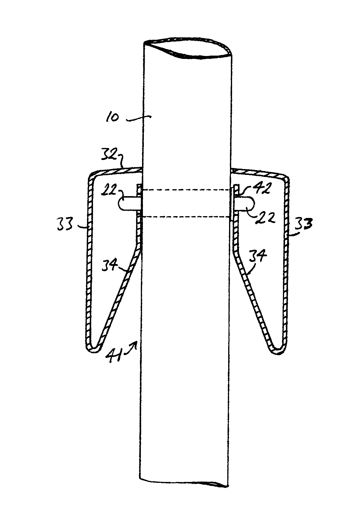
The invention is a fencing panel that can be easily assembled on-site from a kit of parts, and makes the installation of fence posts and rails easier for less skilled workers. The panel has return walls that are curved and smooth, making it difficult to remove a panel without damaging it. The open base between the walls allows the panels to pivot about the projections, which prevents rattling and also makes the panels deeper and stronger without creating finger traps or making the panels loose and insecure.

Problems solved by technology

Following assembly, the projections are concealed within the rail so that it is difficult to remove a pale without destroying the panel.
Advantageously, by providing a pair of return walls with smoothly curved opposed surfaces, it is found to be extremely difficult to dislodge a pale by inserting a crowbar or the like into the base of the rail, even where the rail is resiliently deformable to accommodate the projections on the pales during assembly, since the curved surfaces cause the crowbar to slip out of the rail without gaining a purchase.

Method used


Image

  • Self-raking fence panel and rail, kit of parts, and method of assembly and installation
  • Self-raking fence panel and rail, kit of parts, and method of assembly and installation
  • Self-raking fence panel and rail, kit of parts, and method of assembly and installation

Examples


Embodiment Construction

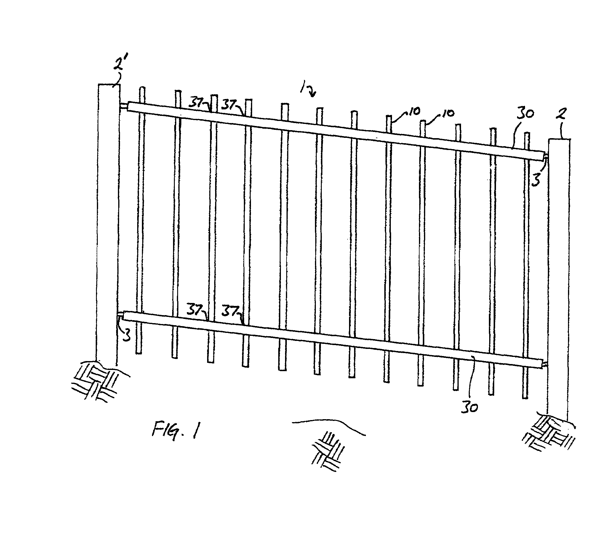
[0043]Referring to FIG. 1, a first self-raking fence panel 1 comprises a plurality of pales 10 supported by a pair of identical rails 30. The rails have a plurality of apertures 37 for receiving the pales, and are mounted between two vertical posts 2, 2′ by conventional adjustable fixings 3. The pales are pivotably mounted in the rails, enabling the panel to be raked as shown by adjusting the rails to lie parallel with the slope of the ground.

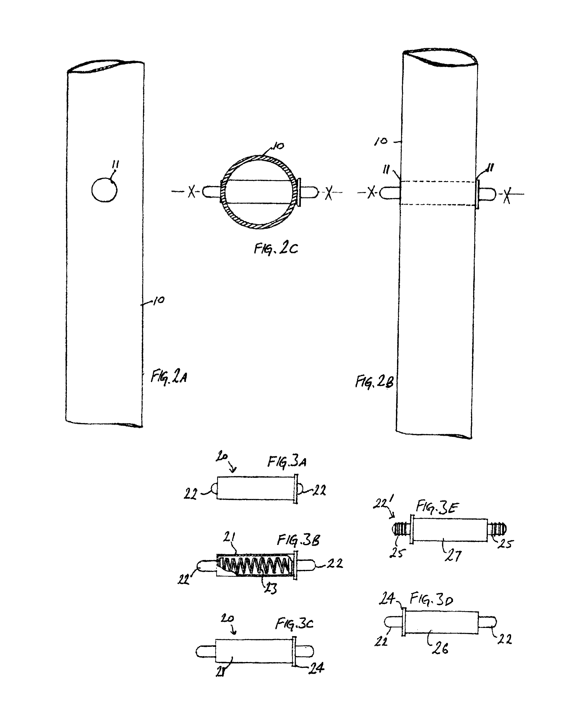
[0044]Referring to FIGS. 2A-2C and FIGS. 3A-3C, each pale 10 comprises a steel tube with a pair of opposed apertures 11 formed in the wall of the tube along a transverse axis X-X of the pale so as to form a cross-bore. An insert, comprising a spring assembly 20 is adapted to be inserted into the cross-bore via the apertures 11 so that it lies along the transverse axis X-X of the pale. The spring assembly comprises a tubular body 21 which supports a pair of projections 22; the projections are resiliently biased outwardly from the ends of the bod...


PUM

PropertyMeasurementUnit
Volumeaaaaaaaaaa
Volumeaaaaaaaaaa
Volumeaaaaaaaaaa

Abstract

A self-raking fence panel (1) comprises a pair of invert, U-shaped rails (30), each having a horizontal central wall (32) with apertures (37) for receiving a plurality of pales (10), a pair of outer side walls (33), and rigid or resilient, integral internal return walls (34, 134) defining downwardly diverging ramped surfaces (40, 135) and a pair of recesses (42, 136) adjacent each aperture. The pales are provided with spring biased pins (20) which are compressed by the ramped surfaces (40, 135) as the pale is pushed up through the respective aperture (37) until the pins lock in the recesses (42, 136). Alternatively, the pales may have rigid pins (26, 143) which urge the return walls (34, 134) outwardly as the pale is raised until the pins enter the recesses. The fence may be supplied as a kit of parts and assembled on site by fixing the rails (30) to the posts (2, 2′), setting the posts in the ground, and then populating the rails with the pales.

Description

CROSS-REFERENCE TO RELATED APPLICATIONS[0001]This application is a national stage entry of international application number PCT / GB2007 / 050772, having international filing date Dec. 20, 2007, which was published in English, and which claims priority to Great Britain patent application No. GB0625622.6, filed Dec. 22, 2006.BACKGROUND OF THE INVENTION[0002]This invention relates to fences assembled from so-called self-adjusting or self-raking panels, each comprising a plurality of pales supported by two or more rails.[0003]Self-raking fence panels are arranged to permit the pales to be pivotably adjusted through a limited angular range with respect to the rails, so that the rails can be fixed between adjacent vertical posts and adjusted or “raked” to follow the slope of the ground. Once installed, it is important that the fence is as difficult as possible for unauthorised persons to dismantle, so that it can resist vandalism and, where required, provide a secure barrier. Preferably, the...

Claims


Application Information

Patent Timeline
IPC IPC(8): B21F27/00E04H17/14E04H17/16
CPCE04H17/1443E04H17/1439E04H2017/1491Y10T29/49826E04H17/1447E04H17/1448E04H17/14E04H17/1417
Inventor WALMSLEY, ROGER
Owner CRH FENCING & SECURITY GRP UK
Learn More