Kneader/stirrer

a technology of kneader and stirring machine, which is applied in the direction of rotary stirring mixer, transportation and packaging, chemical/physical/physicochemical processes, etc., can solve the problems of insufficient removal of resin stuck on the impeller and the inner wall of the processing chamber, and the device is also not free of problems, so as to increase the degree of polymerization of a polycondensation resin and smooth stirring operation. , the effect of low polymerization degr

Active Publication Date: 2016-08-30
KURIMOTO LTD
View PDF16 Cites 2 Cited by
  • Summary
  • Abstract
  • Description
  • Claims
  • Application Information

AI Technical Summary

Benefits of technology

[0007]An object of the present invention is to provide a kneader / stirrer which have a high self-cleaning ability and thus can be operated for a long period of time.
[0011]In this arrangement, each of the pair of first and second impellers is preferably fixed to the corresponding rotary shaft such that the axis of the rotary shaft coincides with a point of the corresponding impeller that is offset from the center of the regular triangular sectional shape in the direction opposite to the direction toward one of the three apexes. With this arrangement, each impeller can be rotated in a balanced manner with the one of its apexes always facing outwardly of the device, which in turn ensures smooth stirring operation.
[0012]The present invention is especially effectively applicable to an arrangement in which the kneader / stirrer is used as a polymerizer for increasing the degree of polymerization of a polycondensation resin with a low polymerization degree which is supplied into the processing chamber as the material to be processed, by stirring the polycondensation resin supplied.
[0013]If the kneader / stirrer is used as such a polymerizer, the impellers preferably each have a lightening hole such that the polycondensation resin forms a film in the lightening hole while the polycondensation resin is being stirred by the impellers. This promotes polymerization reactions and volatilization of e.g. solvents, thus making it possible to efficiently treat resin.
[0014]In the kneader / stirrer according to the present invention, at least a pair of first and second impellers fixed to two rotary shafts extending in the processing chamber parallel to each other at the same axial position in an offset state have identical regular triangular shapes and are arranged such that when they are eccentrically pivoted, one of the apexes of one of the pair of impellers scrape off and reliably remove material to be processed adhered to the outer periphery of the other of the pair of impellers. Thus, this kneader / stirrer is superior in self-cleaning ability to conventional kneader / stirrers, which use disk-shaped impellers, and also can be stably operated for a long period of time.

Problems solved by technology

The kneader / stirrer (polymerizer) disclosed in JP Patent 4112908 has a problem in that resin tends to be strongly adhered to the outer peripheries of the impeller and the inner wall of the processing chamber, so that solidified resin tends to become wedged between adjacent impellers or between an impeller and the inner wall of the processing chamber, thus causing trouble during operation.
But since the impellers are disk-shaped members, they cannot sufficiently remove resin stuck on the impellers and the inner wall of the processing chamber.
Thus this device is also not free of the problem resulting from solidified resin becoming wedged between parts.

Method used


Image

  • Kneader/stirrer
  • Kneader/stirrer
  • Kneader/stirrer

Examples


Embodiment Construction

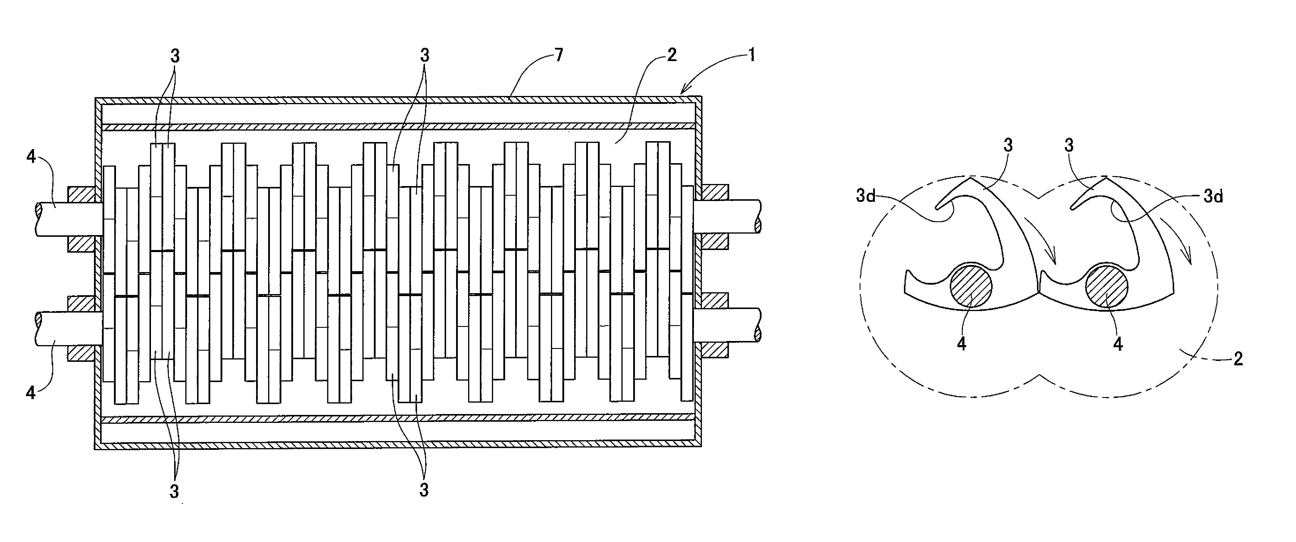
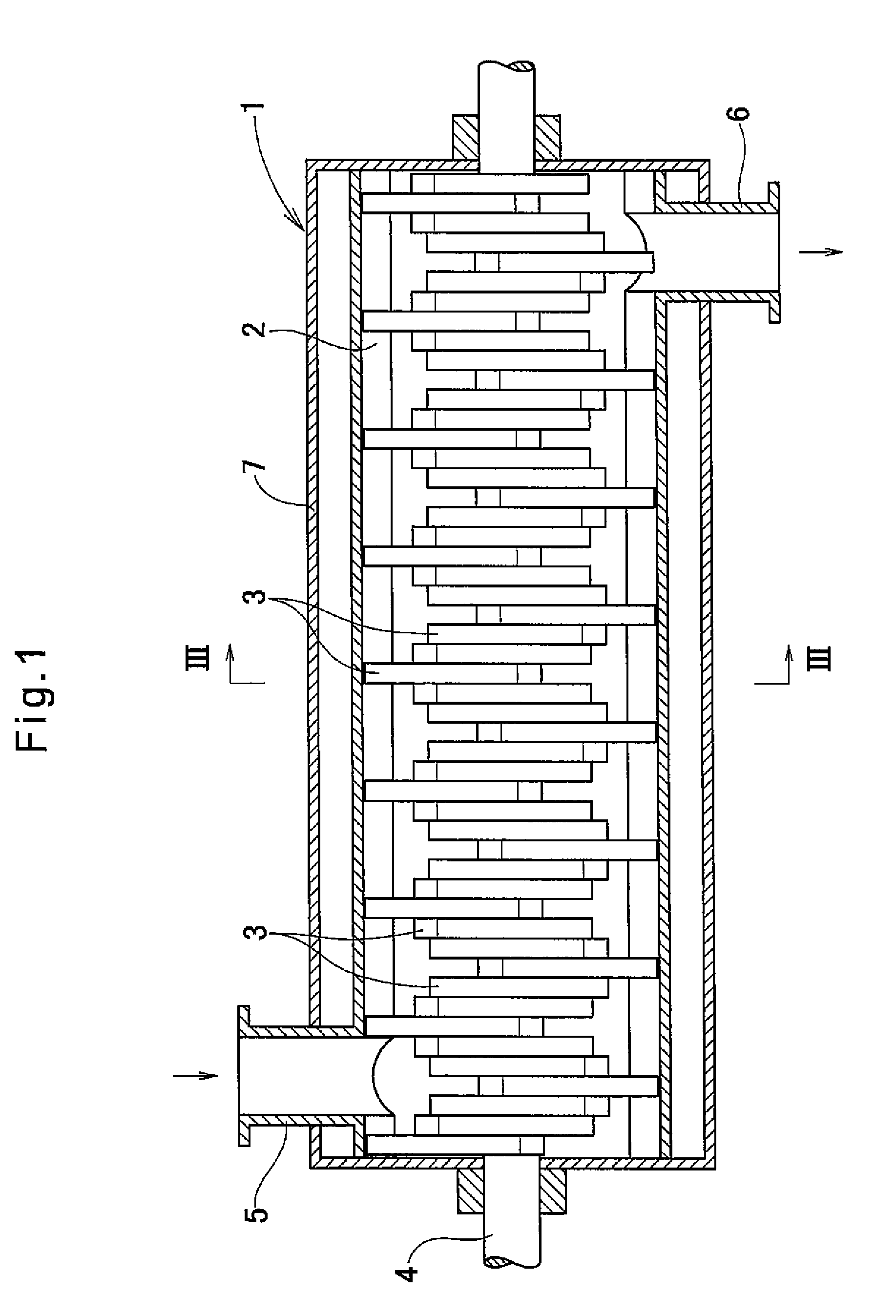
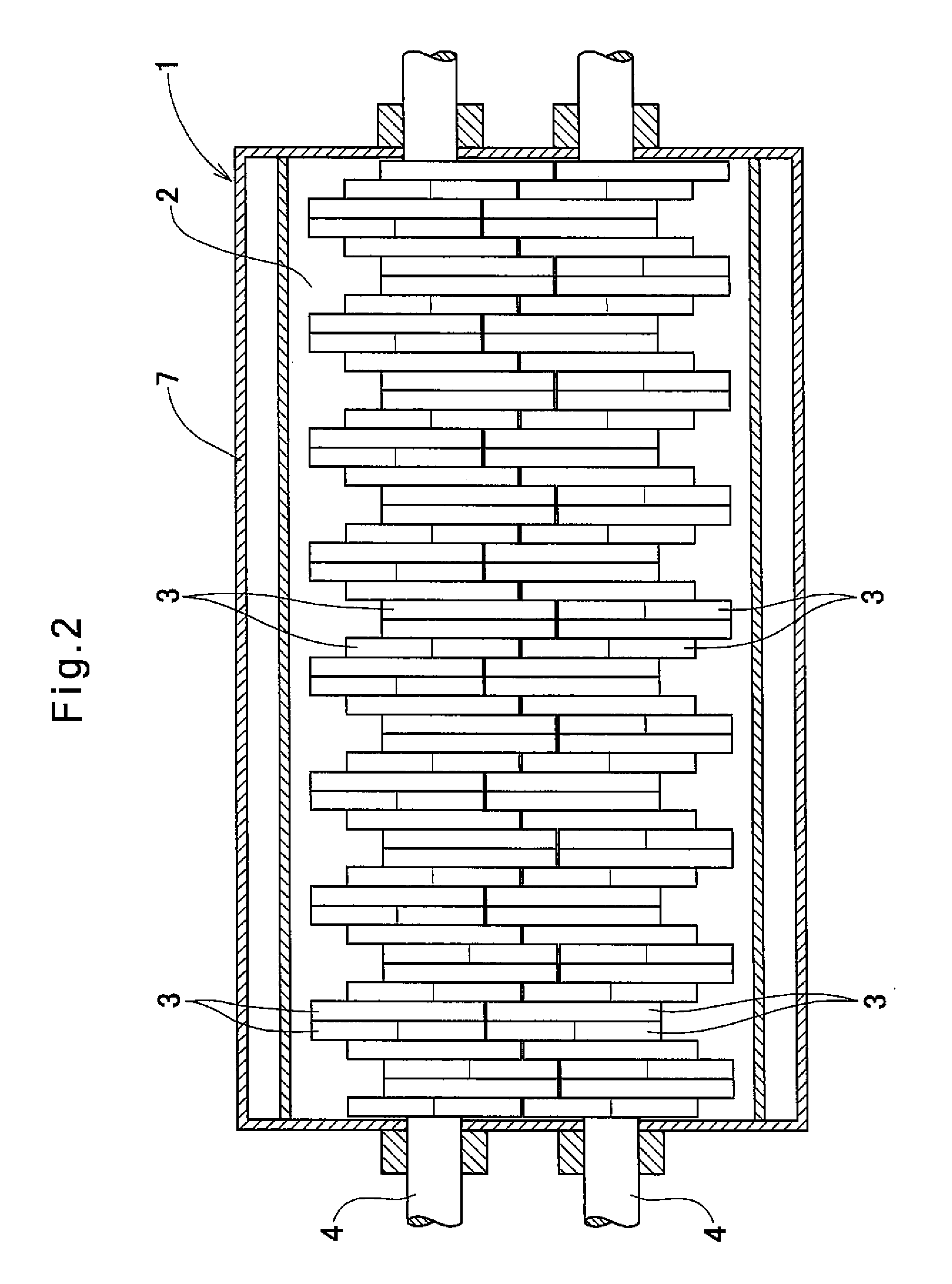
[0024]The embodiments of the present invention are now described with reference to the drawings. FIGS. 1 to 6(c) show the kneader / stirrer embodying the present invention. This kneader / stirrer is used as a polymerizer for increasing the degree of polymerization of a polycondensation resin with a low polymerization degree which has been fed into the kneader / stirrer, by stirring this resin. As shown in FIGS. 1 to 3, this kneader / stirrer includes a tubular casing 1 having a section formed by two circles equal in diameter and overlapping with each other, and defining therein a processing chamber 2, and two rotary shafts 4 mounted in the processing chamber 2 to extend parallel to each other and each carrying a large number of impellers 3 arranged in the axial direction.

[0025]The casing 1 has a supply port 5 provided at one end on top of the casing 1, and a discharge port 6 at the other end on the bottom of the casing 1. The casing 1 has its outer circumferential surface covered with a jac...


PUM

PropertyMeasurementUnit
rotational speedaaaaaaaaaa
degree of polymerizationaaaaaaaaaa
viscosityaaaaaaaaaa

Abstract

A kneader / stirrer includes two rotary shafts extending parallel to each other in the processing chamber, and first and second regular triangular impellers mounted to the respective rotary shafts. The first impellers are located at the same axial positions as the respective first impellers. The impellers are fixed to the respective rotary shafts at points offset from the centers of the respective impellers in a predetermined direction by a predetermined distance such that when the two rotary shafts rotate in the same direction at the same speed, each pair of first and second impellers are eccentrically pivoted, with one apex of one of the pair of impellers kept in contact with or in close proximity to the contour of the other impeller, thereby scraping off polycondensation resin (material to be processed) adhered to the other impeller.

Description

TECHNICAL FIELD[0001]The present invention relates to a kneader / stirrer for kneading and stirring e.g. powder, a liquid or a high-viscosity fluid.BACKGROUND ART[0002]Some of known kneader / stirrers for kneading and stirring powder liquids and high-viscosity fluids are used as polymerizers for increasing the degree of polymerization of a polycondensation resin with a low degree of polymerization which has been supplied into the kneader / stirrer as a material to be processed, by stirring the resin supplied (see e.g. JP Patent 4112908 and JP Utility Model Publication 62-123238U).[0003]The kneader / stirrer (polymerizer) disclosed in JP Patent 4112908 includes a tubular casing defining therein a processing chamber, and a large number of plate-shaped impellers mounted in the processing chamber so as to be arranged in the axial direction and configured to stir a polycondensation resin. The impellers have lightening holes. The lightening holes enhance polymerization reactions and evaporation o...

Claims


Application Information

Patent Timeline
Patent Type & Authority Patents(United States)
IPC IPC(8): B29B7/80C08F2/01B01J19/20B01J19/18B01J19/00B29B7/48B01F7/00B01F7/04
CPCB01F7/00208B01F7/00225B01F7/00275B01F7/003B01F7/042B29B7/481B29B7/805C08F2/01B01J19/0066B01J19/1887B01J19/20B01J2219/00094B01J2219/00168B29B7/489B29B7/826B01F27/093B01F27/1123B01F27/11251B01F27/091B01F27/702
Inventor FUJII, ATSUSHIYAMASAKI, KOJIFUKUMOTO, KAZUNORI
Owner KURIMOTO LTD
Why Eureka
Try Eureka