
Truss spar vortex induced vibration damping with vertical plates

a technology of vertical plates and spars, applied in floating buildings, special-purpose vessels, transportation and packaging, etc., can solve the problems of complex operation of floating offshore platforms, viv is particularly susceptible to vortex-induced vibration (viv) or vortex-induced motion, and viv is reduced. , the effect of reducing viv

Active Publication Date: 2016-08-23
TECH FRANCE SA
View PDF7 Cites 0 Cited by
  • Summary
  • Abstract
  • Description
  • Claims
  • Application Information

AI Technical Summary

Benefits of technology

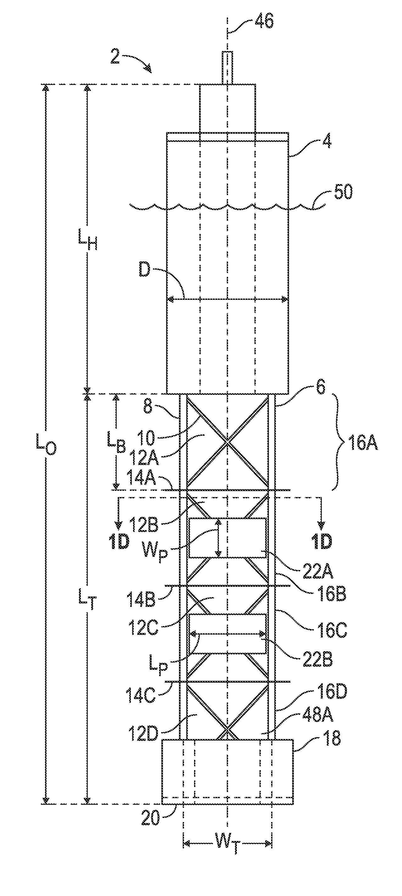
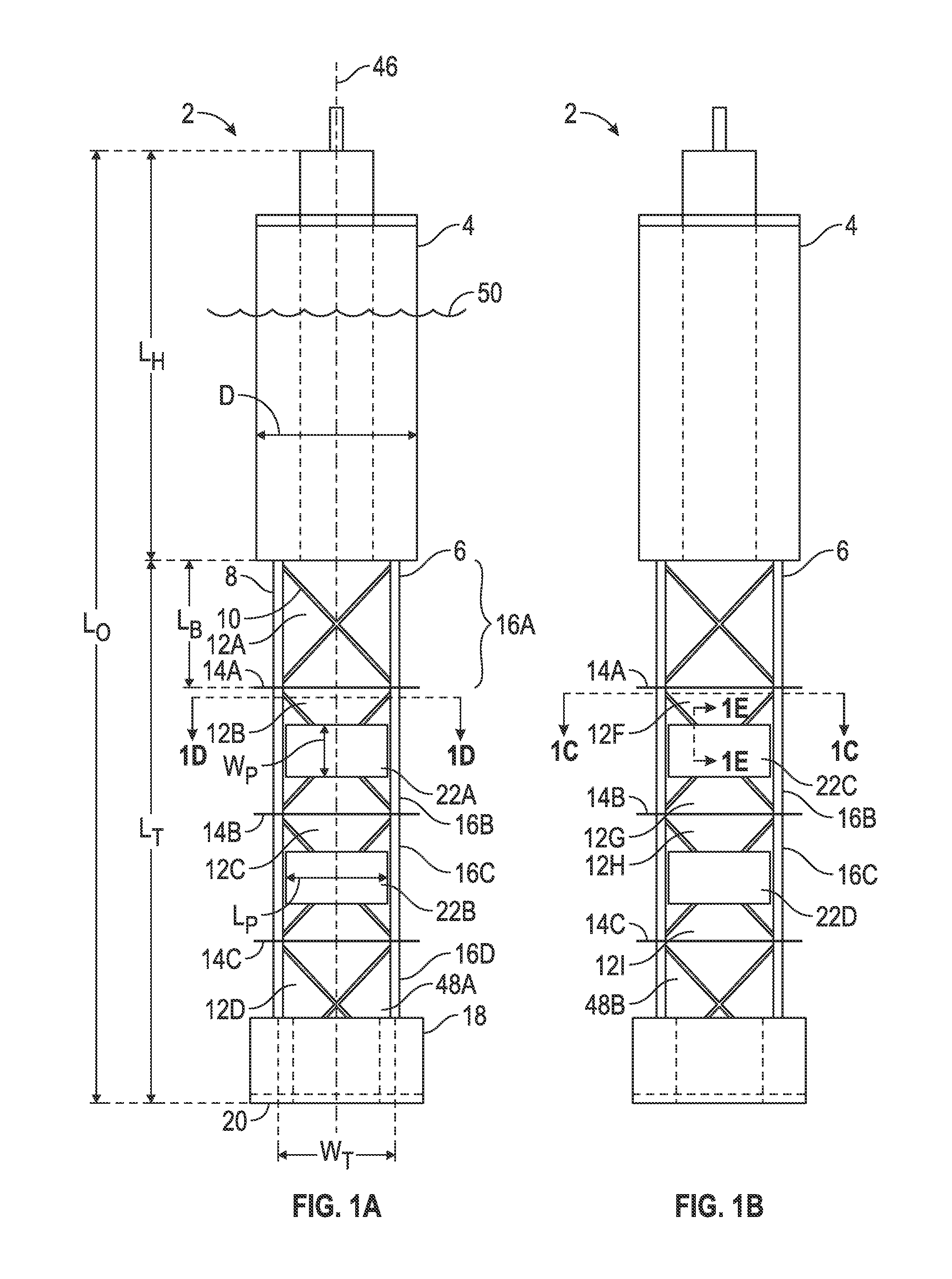
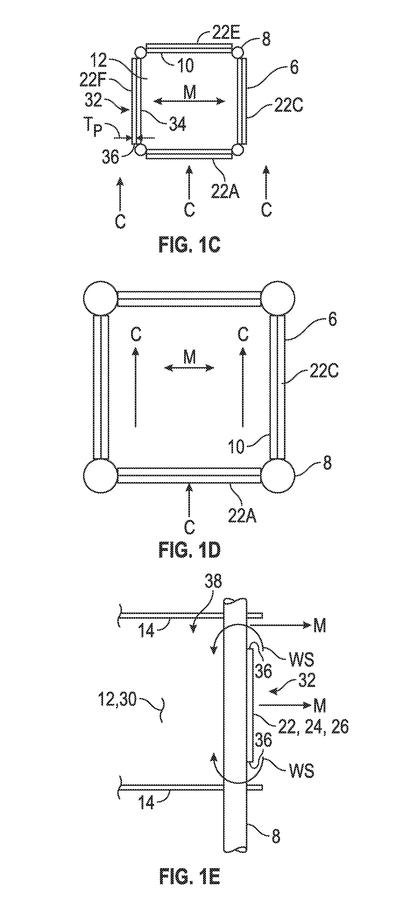
[0021]The disclosure provides a system for reducing vortex-induced-vibration (VIV) in an offshore platform, comprising: a hull of the offshore platform; a truss of the offshore platform configured to be at least partially submerged below a surface of water, the water having a current flow; and one or more side plates tangentially coupled around a periphery of the truss, the hull, or both, the side plates forming an open space for water on both sides of the plates that is transverse to the current flow, the tangential side plates being configured to cause water separation around the side plates when the offshore platform moves transversely to the current flow and reduce VIV in the offshore platform by at least 20% of a VIV in the offshore platform without the tangential side plates.
[0022]The disclosure also provides a system for reducing vortex-induced-vibration (VIV) in an offshore platform, comprising: a hull of the offshore platform having a diameter; a truss of the offshore platform configured to be at least partially submerged below a surface of water, the water having a current flow; and one or more tangential side plates tangentially coupled around a periphery of the truss, the hull, or both, the side plates forming an open space for water on both sides of the plates that is transverse to the current flow, the tangential side plates being configured to cause water separation around the plates when the offshore platform moves transversely to the current flow, the side plates being sized for a width of at least 5% of the diameter and a length of at least 15% of the diameter.
[0023]The disclosure further provides a method for reducing vortex-induced-vibration (VIV) in an offshore platform, having a hull; a truss of the offshore platform configured to be at least partially submerged below a surface of water, the water having a current flow; and one or more tangential side plates tangentially coupled around a periphery of the truss, the hull, or both, the tangential side plates forming an open space for water on both sides of the plates that is transverse to the current flow, comprising: separating water flow over one or more edges of the side plates when the offshore platform moves transversely relative to the current flow; generate resistance to the transverse motion on the truss, the hull, or both with the water separation; and reducing the VIV in the offshore platform by at least 20% of a VIV in the offshore platform without the plates.

Problems solved by technology

Although floating offshore platforms may be more complex to operate because of their movement in response to environmental conditions, such as wind and water movement, they are generally capable of operating in substantially greater water depths than are fixed platforms.
For example, because of their elongated, slender shape, they can be relatively more complex to manage during offshore operations under some conditions than other types of platforms in terms of, for example, control over their trim and stability.
In particular, because of their elongated, slender shape, spar platforms may be particularly susceptible to vortex-induced vibration (VIV) or vortex induced motion (VIM) (herein collectively, “VIV”), which may result from strong water currents acting on the hull of the platform.
VIV is an important cause of fatigue damage of offshore oil exploration and production platforms, risers, and other structures.
When lock-in occurs, large-scale, damaging vibrations can result.
However, strakes can be labor intensive, and difficult to install and transport undamaged to an installation site of the spar platform.

Method used


Image

  • Truss spar vortex induced vibration damping with vertical plates
  • Truss spar vortex induced vibration damping with vertical plates
  • Truss spar vortex induced vibration damping with vertical plates

Examples


Embodiment Construction

[0042]The Figures described above and the written description of specific structures and functions below are not presented to limit the scope of what Applicant has invented or the scope of the appended claims. Rather, the Figures and written description are provided to teach any person skilled in the art how to make and use the inventions for which patent protection is sought. Those skilled in the art will appreciate that not all features of a commercial embodiment of the inventions are described or shown for the sake of clarity and understanding. Persons of skill in this art will also appreciate that the development of an actual commercial embodiment incorporating aspects of the present inventions will require numerous implementation-specific decisions to achieve the developer's ultimate goal for the commercial embodiment. Such implementation-specific decisions may include, and likely are not limited to, compliance with system-related, business-related, government-related and other...


PUM


Abstract

The disclosure provides a system and method of reducing vortex induced vibration (VIV) with a plurality of tangentially disposed side plates having an open space on both faces transverse to a current flow of water. The side plates cause water separation around the plates with transverse VIV movement of the platform caused by the current flow against the platform, and the tangential side plates resist the VIV movement of the platform from the current. The side plates can be disposed tangentially around a periphery of an open truss structure below the hull of a spar platform. In another embodiment, the tangential side plates can be disposed tangentially away from a periphery of a hull to form a gap with an open space between the plates and the hull.

Description

CROSS REFERENCE TO RELATED APPLICATIONS[0001]This international patent application claims the benefit of priority to U.S. Provisional Application No. 61 / 701,876, filed Sep. 17, 2012.STATEMENT REGARDING FEDERALLY SPONSORED RESEARCH OR DEVELOPMENT[0002]Not applicable.REFERENCE TO APPENDIX[0003]Not applicable.BACKGROUND OF THE INVENTION[0004]1. Field of the Invention[0005]The disclosure relates to a system and method for reducing vibrations on floating platforms for drilling and production. More particularly, the disclosure relates to a system and method to reduce vortex-induced vibrations for a floating platform, such as a spar offshore platform.[0006]2. Description of the Related Art[0007]Offshore oil and gas drilling and production operations typically involve a platform, sometimes called a rig, on which the drilling, production and storage equipment, together with the living quarters of the personnel manning the platform, if any, may be mounted. Floating offshore platforms are typi...

Claims


Application Information

Patent Timeline
Patent Type & Authority Patents(United States)
IPC IPC(8): E02B17/00B63B39/00B63B35/44
CPCB63B35/4413B63B39/005E02B17/0017B63B2035/442E02B2017/0073E02B2017/0095B63B35/44
Inventor LAMBRAKOS, KOSTAS F.KOO, BONJUN
Owner TECH FRANCE SA
Learn More