
Device for feeding a fluid to a vessel to be filled

a technology for feeding fluids and tires, applied in the direction of tyre-inflating valves, tyre measurements, functional valve types, etc., can solve the problem of supplying too much air to tires, and achieve the effect of safe feeding fluids, without running the risk of overfilling the vessel or tir

Active Publication Date: 2016-08-23
BUTLER ENG & MARKETING
View PDF6 Cites 0 Cited by
  • Summary
  • Abstract
  • Description
  • Claims
  • Application Information

AI Technical Summary

Benefits of technology

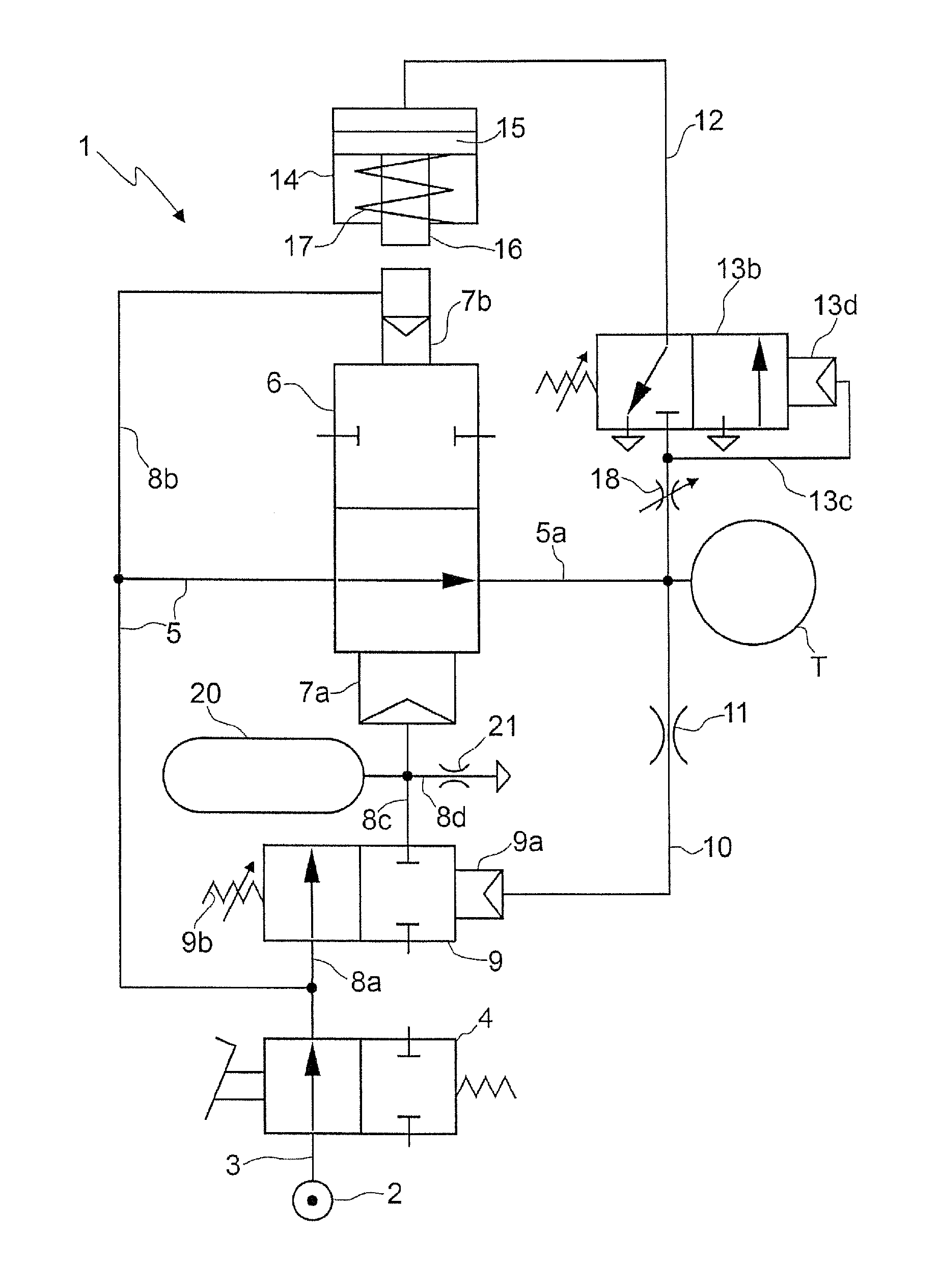
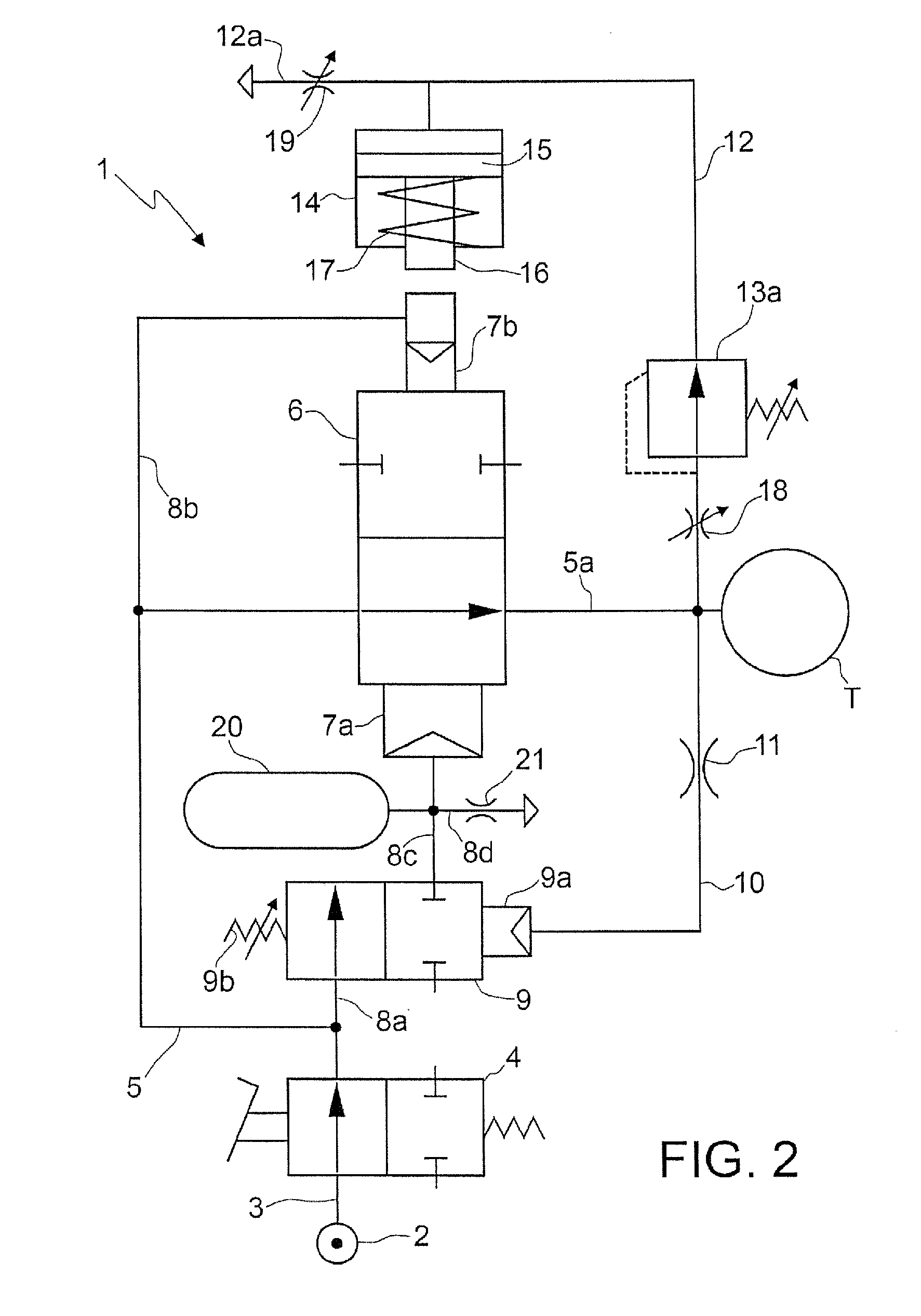
The present invention provides a device for safely feeding fluid to a vessel, such as a tire, without risking overfilling. The device is easy and cost-effective to produce.

Problems solved by technology

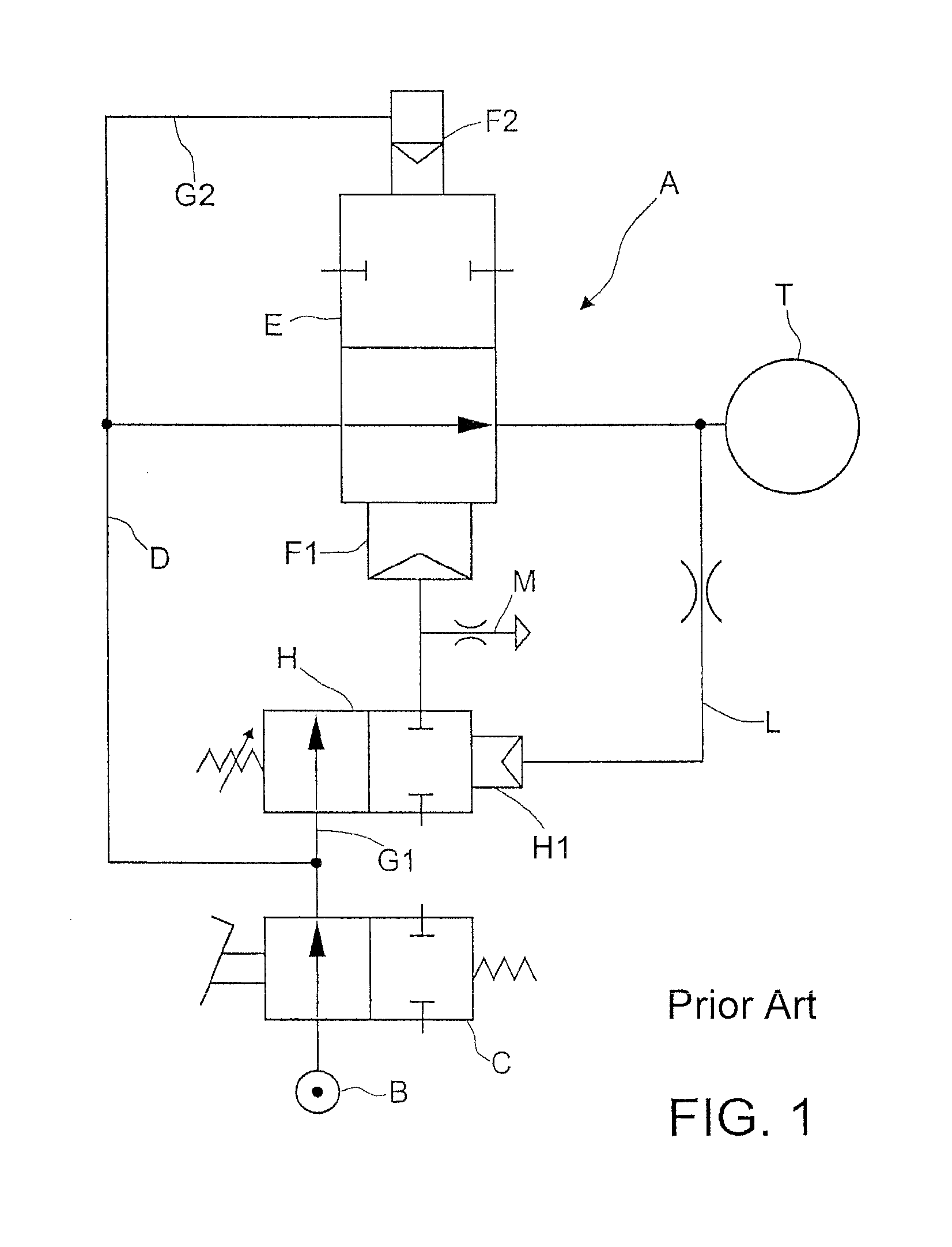
With such devices, should the calibrated interception valves fail, particularly should they fail in open condition, it is understood that one would risk supplying too much air to the tire (should the operator not be careful during inflation and not release the pedal), ruining it if not making it explode.

Method used


Image

  • Device for feeding a fluid to a vessel to be filled
  • Device for feeding a fluid to a vessel to be filled
  • Device for feeding a fluid to a vessel to be filled

Examples


Embodiment Construction

[0046]First, with reference to FIG. 1, a device A is illustrated for inflating a tire T according to the prior art, which comprises a pressurized air insertion opening B in fluid communication with a pressurized air source, hence a shut-off valve C, e. g. controllable by an operator by means of a suitable pedal, and a line D for supplying the pressurized air to the tire T. On the supply line D, a valve E is provided for that can be moved transversely to the supply line D between a first position in which it allows the passage of fluid on the supply line D towards the tire T and a second position in which it obstructs such passage. The device then comprises two chambers or cylinders, one larger F1 and one smaller F2, each connected by a respective branch line G1, G2 from the supply line D. The two cylinders F1, F2 are arranged one opposite to the other with respect to the supply line D; in addition, a respective end of the valve E or of a stem or pin thereof is slidably mounted in ea...


PUM


Abstract

The present invention relates to a device for feeding a fluid to a vessel (T), including a fluid inflow or inlet opening, a distribution valve placed between the inlet opening and the vessel (T), a fluid supply line between the distribution valve and the vessel, and a valve member intercepting the supply line and movable between a first position and a second position.

Description

CROSS REFERENCE TO RELATED APPLICATIONS[0001]This application claims the benefit of priority from Italian Patent Application No. VR2012A000246 filed on Dec. 20, 2012 and from Italian Patent Application No. VR2013A000121 filed May 22, 2013, each of the contents of which are incorporated by reference.TECHNICAL FIELD OF THE INVENTION[0002]The present invention regards a device for feeding a fluid to a vessel to be filled, more particularly a device for inflating a tire to a pre-established pressure.DESCRIPTION OF RELATED ART[0003]In order to inflate tires to a specific pressure, many devices have been provided for up to now, including some equipped with an air supply line intercepted by a valve member, which is movable between an open or opening position in which it allows the passage of air between the supply line and the tire and a second position in which it obstructs such passage. More particularly, the valve member comprises or has ends slidably mounted in two cylinders, one large...

Claims


Application Information

Patent Timeline
Patent Type & Authority Patents(United States)
IPC IPC(8): F16K15/20B60C29/06B60C23/00
CPCB60C29/068B60C23/003Y10T137/36B60C23/00354B60C23/00372
Inventor GONZAGA, TULLIOSANTI, SILVANO
Owner BUTLER ENG & MARKETING
Learn More