Mount device for outboard motor

a technology for mounting devices and outboard motors, which is applied in waterborne vessels, marine propulsion, vessel construction, etc., can solve the problems that the elastic body cannot prevent interference between the members on the outboard motor body side, and achieve the effect of reducing the requirement for machining accuracy, reducing the manufacturing cost of the right-left, and improving steering respons

Active Publication Date: 2016-08-16
SUZUKI MOTOR CORP
View PDF16 Cites 0 Cited by
  • Summary
  • Abstract
  • Description
  • Claims
  • Application Information

AI Technical Summary

Benefits of technology

[0019]According to the present invention of the characters mentioned above, a gap between the respective abutment surfaces of the lateral displacement restriction mount section (i.e., lateral displacement restriction mount section including a rolling direction and a yaw direction) and the opposing member is decreased during the high-speed rotation of the engine and during the forward movement of the hull, and therefore, a displacement restricting function during the high-speed rotation of the engine and a steering response can be improved. Furthermore, since the gap between the respective abutment surfaces of the above lateral displacement restriction mount section and the opposing member is set to be large enough not to interfere the abutment surfaces with each other even by the vibration of the engine during the low-speed rotation of the engine, it is possible to reduce a requirement for machining accuracy of the above lateral displacement restriction mount section, and to reduce a manufacturing cost of the right-left etc. displacement restriction mount.

Problems solved by technology

However, when a large load is applied to the outboard motor body as in a case in which a thrust of the outboard motor body rapidly changes, only the elastic body may not be able to prevent interference between a member on the outboard motor body side (e.g., an engine holder) and a member on the attachment device side (e.g., a swivel bracket).

Method used


Image

  • Mount device for outboard motor
  • Mount device for outboard motor
  • Mount device for outboard motor

Examples


Embodiment Construction

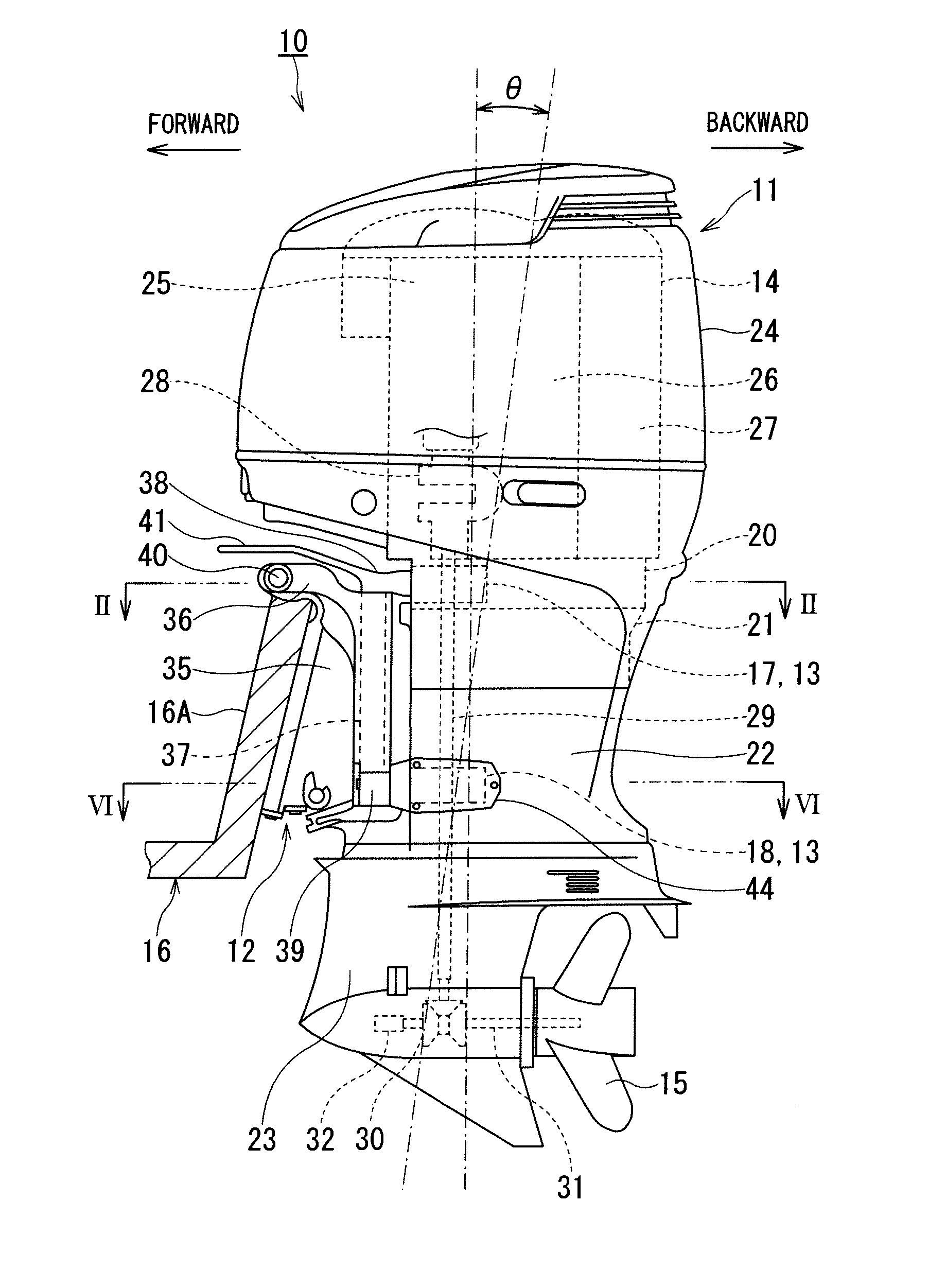
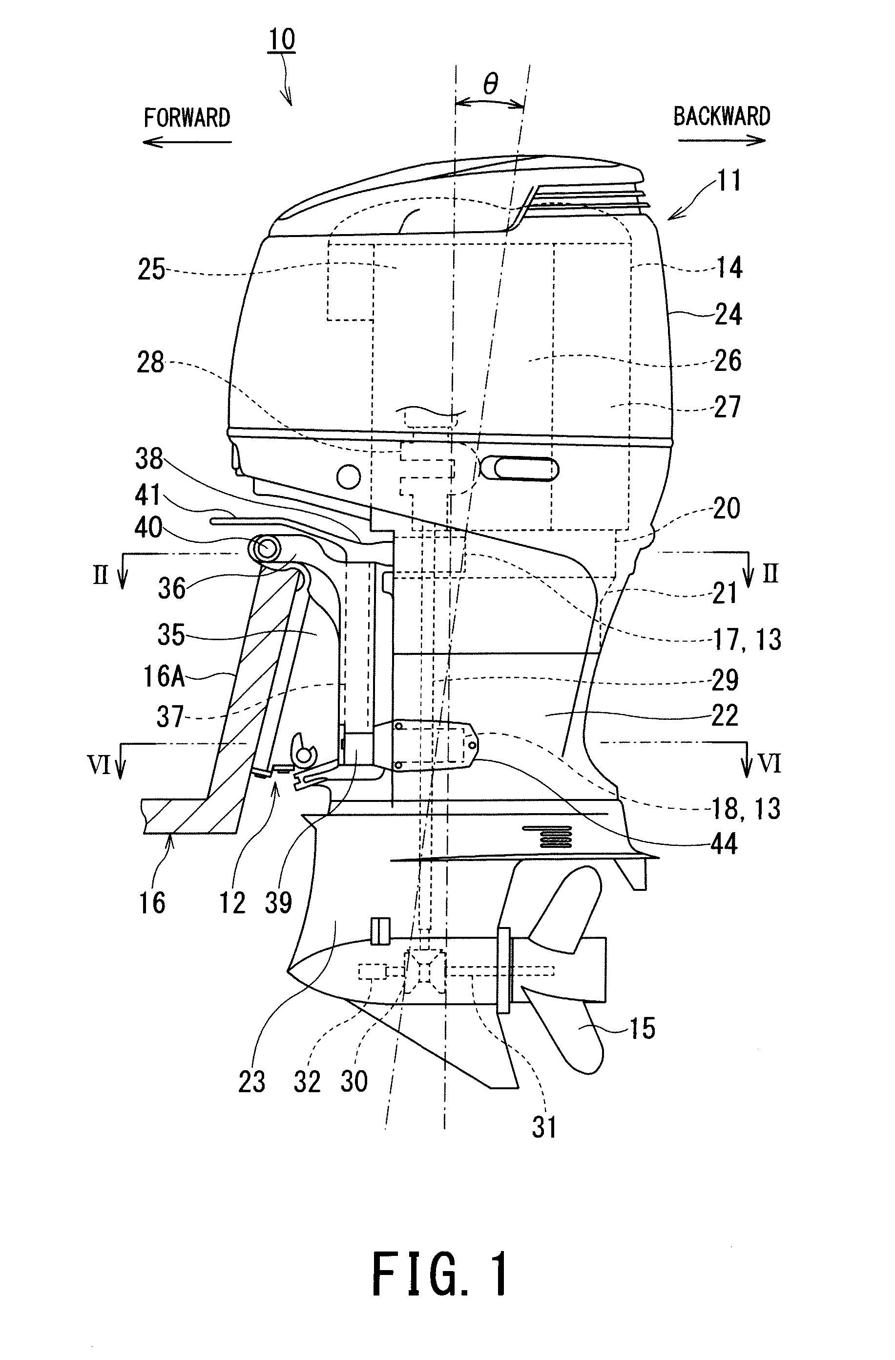
[0030]An embodiment for carrying out the present invention is described hereinafter with reference to the accompanying drawings. FIG. 1 is a left side view illustrating an outboard motor to which one embodiment of a mount device for an outboard motor according to the present invention is applied. It is to be noted that terms indicating directions such as “upper”, “lower”, “right”, “left” and like indicating direction are used herein with reference to an illustrated state or in a state in which the outboard motor is attached to a hull.

[0031]As shown in FIG. 1, an outboard motor 10 includes an outboard motor body 11 that generates a thrust to a front side or a rear side of the outboard motor by transmitting a drive force of a mounted engine 14 to a propeller 15 to rotate the propeller 15, an attachment bracket device 12 as an attachment device that supports the outboard motor body 11 and attaches the outboard motor body 11 to a transom 16A of a hull 16, and a mount device 13 that is d...


PUM


Abstract

An outboard motor having an outboard motor body generating a thrust by rotating a propeller that is driven by an engine mounted to the outboard motor and an attachment device for attaching the outboard motor body to a hull. The outboard motor includes a mount device having an upper mount and a lower mount arranged between the outboard motor body and the attachment device for attaching the outboard motor body to the hull and supports an upper portion and a lower portion of the outboard motor body, respectively. The mount device also includes an anti-vibration unit and a displacement restriction unit. The lateral displacement restricting mount section and a member opposing the lateral displacement restricting mount section abut against each other with the abutment surfaces inclined with respect to a longitudinal direction of the outboard motor body.

Description

PRIORITY CLAIM[0001]This patent application is a U.S. National Phase of International Patent Application No. PCT / JP2013 / 082010, filed 28 Nov. 2013, which claims priority to Japanese Patent Application No. 2012-267609, filed 6 Dec. 2012, the disclosures of which are incorporated herein by reference in their entirety.TECHNICAL FIELD[0002]The present invention relates to a mount device for an outboard motor that is arranged between an outboard motor body and an attachment device that attaches the outboard motor body to a hull.BACKGROUND ART[0003]Generally, in a mount device for an outboard motor disposed between an outboard motor body and an attachment device through which the outboard motor body is attached to a hull, a mount unit including an upper mount unit and a lower mount unit which are arranged in an upper portion and a lower portion of the outboard motor body, and vibration of an engine is prevented from transmitting to the hull by providing an elastic body, such as rubber mat...

Claims


Application Information

Patent Timeline
Patent Type & Authority Patents(United States)
IPC IPC(8): B63H1/15B63H21/30B63H20/08B63H20/06B63H20/10
CPCB63H20/08B63H20/06B63H20/10B63H21/30
Inventor SHOMURA, NOBUYUKIYAMAZAKI, AKINORI
Owner SUZUKI MOTOR CORP
Why Eureka
Try Eureka