
Biomaterial and method for its realisation

a biomaterial and material technology, applied in the field of biomaterials, can solve the problems of poor mechanical resistance, inability to absorb, and poor mechanical resistance, and achieve the effects of improving mechanical resistance, and reducing the resistance of biomaterials

Active Publication Date: 2016-08-09
TECRES SPA
View PDF7 Cites 1 Cited by
  • Summary
  • Abstract
  • Description
  • Claims
  • Application Information

AI Technical Summary

Benefits of technology

[0024]Within such technical task, the present invention aims at providing a biomaterial adapted to be interfaced with organic tissues without creating adverse reactions in the tissue or at systemic level.
[0025]Another object of the present invention is that of providing a biomaterial having bioinductive and bioconductive characteristics, in particular osteoinductive and osteoconductive. A further object of the present invention is that of providing a biomaterial adapted to allow the colonization—therein—of the organic tissue with which it comes into contact, simultaneously guaranteeing good mechanical resistance characteristics.
[0029]Another object of the present invention is that of providing a method for obtaining a biomaterial adapted for allowing colonization—therein—of the organic tissue with which it comes into contact, simultaneously guaranteeing good mechanical resistance characteristics. Another object of the present invention is that of providing a method that can be easily obtained by clinicians and technicians using the materials currently available in the market.
[0030]Still another object of the present invention is that of providing a method that is inexpensive.
[0032]An important advantage attained by the biomaterial according to the present invention is that of having the possibility of being present in at least two versions: in solid form, possibly preformed and resizable through the common orthopaedic equipments according to the prior art, or in form of a pasty fluid, which can possibly be injected or applied onto the prearranged seat through known syringe, blade means or the like.
[0033]A further advantage lies in the possibility of applying the biomaterial according to the present invention through the techniques of the prior art and universally known by clinician, trained for use thereof, thus without requiring retraining the personnel intended to use and apply such biomaterial.

Problems solved by technology

However such materials reveal some drawbacks.
However, it does not develop a chemical bond with the bone tissue and the mechanical resistance thereof is essentially based on the friction on the interface with the prosthesis and the bone; furthermore, it cannot be absorbed.
Though biocompatible and at least partly absorbable, calcium phosphate cements instead, reveal poor mechanical resistance.
However, the methods for obtaining such materials are extremely complex and difficult and they have not lead to any commercial product up to date; furthermore, though potentially osteoinductive and osteoconductive, the polymeric / ceramic materials allow bone colonization solely in the most external and surface area thereof and they are not capable of obtaining a complete in-depth colonization of the bone.
The formation of such fibrous sheath insulates the biomaterial from the bone, prevents integration and regeneration thereof and it is thus harmful, also due to the fact that in such a manner such sheath constitutes an interruption or discontinuity between the cement and the bone and hinders the possibility of bearing high mechanical loads.
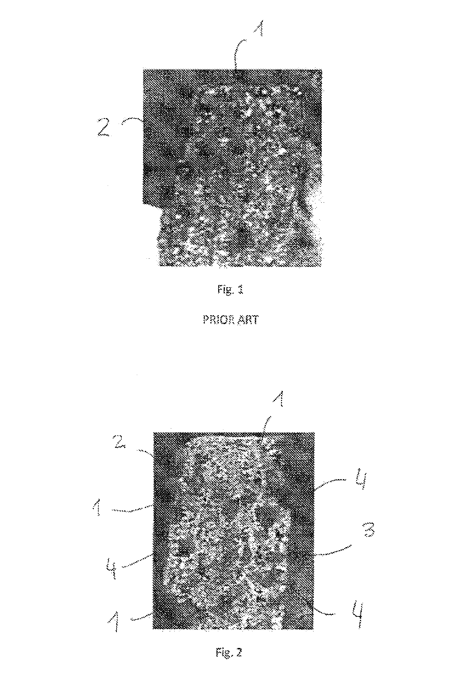
The solutions used currently and described above, however, did not obtain the expected tissue regeneration and implantation, as visible in FIG. 1, due to the fact that the spread porosity does not have cavities larger than 100 microns.
Thus, the use of such biomaterials is limited to a bone filler not subjected to direct loads.
Actually, such materials are used as cranial prosthesis, which however, if subjected to impacts or loads, can break without guaranteeing suitable resistance characteristics required even in such part of the human body.
The previously described biomaterials do not meet all the requirements suitable for supporting and possibly quickening such tissue growth.

Method used


Image

  • Biomaterial and method for its realisation
  • Biomaterial and method for its realisation

Examples


Embodiment Construction

[0041]In the present disclosure, the term biomaterial is used to indicate material of any type or origin capable of interfacing with a biological system with the aim of increasing, treating or substituting any organ tissue or body function; the term bioinductivity is used to indicate the capacity of the biomaterial to cause the new-formation of the tissue with which such biomaterial is interfaced; the term bioconductivity is used to indicate the capacity of the biomaterial to create a suitable support, adapted to allow the colonisation of the progenitor cells of the tissue with which such material is interfaced and capable of guaranteeing survival and proliferation thereof.

[0042]The biomaterial according to the present invention is a biocompatible composite material comprising a component adapted to form a porous structural matrix.

[0043]Such component adapted to form a porous structural matrix may comprise polymeric components, pure metal components or made of alloy and / or ceramic c...


PUM

PropertyMeasurementUnit
sizeaaaaaaaaaa
biocompatibleaaaaaaaaaa
dimensionaaaaaaaaaa

Abstract

Porous biocompatible composite biomaterial, useable as a drug delivery system or as spacer or as bone substitute, such as for example for filling bone lacunae or for substituting damaged parts of bone tissue, or for fixing prosthesis of various types, or for thickening bones weakened by illness such as osteoporosis or the like, including a component adapted to form a porous structural matrix and a soluble component, wherein the soluble component is in form of powder and granules or other similar agglomerates so as to have mechanical support characteristics and osteoinductive and osteoconductive characteristics in the entire volume occupied by the biomaterial, and a method for obtaining the biomaterial.

Description

TECHNICAL FIELD OF THE INVENTION[0001]The present invention regards a biomaterial useable in the medical field, having high characteristics of integration with the biological system in which it is interfaced, bioinductivity and bioconductivity characteristics.[0002]The present invention further regards a method for obtaining a biomaterial having high characteristics of integration with the biological system in which it is interfaced, bioinductivity and of bioconductivity characteristics.DESCRIPTION OF RELATED ART[0003]Ceramic and / or polymeric biomaterials substantially used for fixing prosthesis or as bone substitutes are currently the most commonly used in the field of biomaterials, in particular biomaterials useable in the orthopaedic and surgery field, for filling cavities or lacunae of various origin and type.[0004]Such polymeric biomaterial includes, for example, acrylic bone cement, possibly made up of polymethylmethacrylate (PMMA) and methylmethacrylate (MMA), and absorbable ...

Claims


Application Information

Patent Timeline
Patent Type & Authority Patents(United States)
IPC IPC(8): A61F2/28A61L27/56A61L31/12A61K35/32A61L24/00A61K9/00A61L24/06A61L27/46A61L27/16
CPCA61L24/0036A61L24/0084A61L24/06A61L27/16A61L27/46A61L27/56C08L33/12A61K35/32A61K9/0024A61F2/28A61L2400/16A61L2430/02A61L2430/00
Inventor FACCIOLI, GIOVANNISOFFIATTI, RENZO
Owner TECRES SPA
Learn More