Developer carrying member and image forming apparatus

a development carrying member and image forming technology, applied in the direction of electrographic process apparatus, instruments, optics, etc., can solve the problems of increasing the amount of fogging, and reducing the charge-providing performance of the toner, so as to achieve stable suppression of fogging amount and satisfactory developability

Active Publication Date: 2016-08-02
CANON KK
View PDF20 Cites 1 Cited by
  • Summary
  • Abstract
  • Description
  • Claims
  • Application Information

AI Technical Summary

Benefits of technology

[0006]The present invention has been made in view of the above-mentioned problems, and the present invention is directed to providing a developer carrying member and an image forming apparatus each of which depends on a sheet-passing speed to a small extent while maintaining satisfactory developability, and can stably suppress a fogging amount with time.
[0009]According to the aspects of the present invention, the developer carrying member and the image forming apparatus each of which depends on a sheet-passing speed to a small extent while maintaining satisfactory developability, and can stably suppress a fogging amount with time can be provided.

Problems solved by technology

As a result, a problem resulting from the reduction in charge-providing performance for the toner, e.g., an increase in amount of fogging occurs.
The “fogging” refers to such an image failure that the toner is slightly developed in a white portion (non-printing portion) where no character is originally printed to appear like smearing, and is a problem resulting from the reduction in charge-providing performance for the toner.
However, merely increasing the volume resistance value causes the deterioration of developability such as a low density.

Method used


Image

  • Developer carrying member and image forming apparatus
  • Developer carrying member and image forming apparatus
  • Developer carrying member and image forming apparatus

Examples


embodiment 1

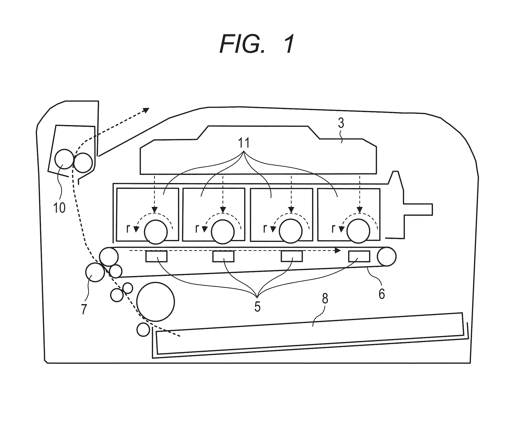
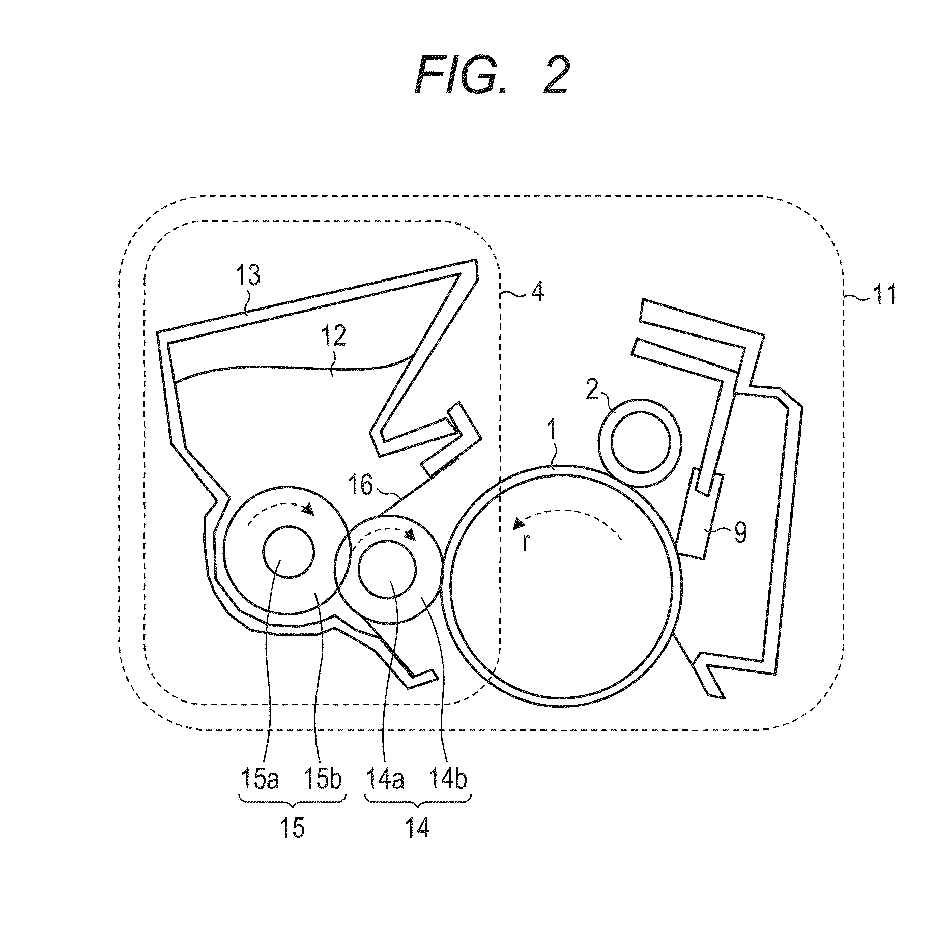
[0038]An image forming apparatus applied to Embodiment 1 of the present invention is illustrated in FIG. 1. In addition, a cartridge 11 constituting the image forming apparatus is illustrated in FIG. 2. In the image forming apparatus, the photosensitive member 1 as an image-bearing member is rotated in a direction indicated by an arrow, and is charged to a uniform electric potential Vd by a charging roller 2 as a charging apparatus. Next, the photosensitive member is exposed by laser light from a laser irradiation apparatus 3 as an exposing apparatus, whereby an electrostatic latent image is formed on its surface. The electrostatic latent image is developed by a developing apparatus 4 to be visualized as a toner image. The visualized toner image on the photosensitive member is transferred onto an intermediate transfer member 6 by a primary transfer apparatus 5, and is then transferred onto paper 8 as a recording medium by a secondary transfer apparatus 7. Transfer residual toner rem...

embodiment 2

[0106]FIG. 3 is a schematic construction view for illustrating a process cartridge of a second embodiment of the present invention. An image recording apparatus of this embodiment is a laser printer of a toner recycle process (cleaner-less system) utilizing a transfer-type electrophotographic process. The redescription of the same points as those of the image recording apparatus of Embodiment 1 is omitted, and different points are described. A characteristic point in this embodiment lies in that transfer residual toner is recycled without the placement of any cleaning blade. The transfer residual toner is recycled so as not to adversely affect any other process such as charging, whereby the toner is recovered in a developing device. Specifically, the following constructions are changed for Embodiment 1.

[0107]The same roller as that of Embodiment 1 is used as the charging roller 2 constituting a charging apparatus, but the charging apparatus further includes a contacting member 17 fo...

example 1

[0108]A developing roller of a structure illustrated in FIG. 4 was produced as described below.

[0109]Used as the electro-conductive mandrel 14a was a product obtained by plating a cored bar made of SUS22 having an outer diameter of 6 mm and a length of 26.5 mm with nickel, and applying and baking PRIMER DY35-051 (trade name, manufactured by Dow Corning Toray Silicone Co., Ltd.) to the resultant. The electro-conductive rubber layer 14b blended with an electro-conductive particle and an electro-semiconductive particle was arranged on the periphery of the mandrel to set the outer diameter of the developing roller 14 to 11.5 mm. Materials for the rubber layer (electro-conductive elastic layer) were as follows: a first layer was a silicone rubber layer (thickness: 2.74 mm) and a second layer was a urethane layer (thickness: 10 μm). The urethane layer was formed of a ZnO particle as the electro-semiconductive particle, a carbon black particle as the electro-conductive particle, and a uret...


PUM


Abstract

Provided is a developer carrying member which depends on a sheet-passing speed to a small extent while maintaining satisfactory developability, and can stably suppress a fogging amount with time. The developer carrying member includes: an electro-conductive mandrel; and an electro-conductive elastic layer, in which: the elastic layer contains a resin j, an electro-semiconductive particle p, and an electro-conductive particle c; and when an electroconductivity of the resin j is defined as σj, a dielectric constant of the resin j is defined as ∈j, an electroconductivity of the electro-semiconductive particle p is defined as σp and a dielectric constant of the electro-semiconductive particle p is defined as ∈p, σj, ∈j, σp, and ∈p satisfy relationships represented by the following formulae (1) and (2), σj, ∈j, σp and ∈p being calculated by an AC impedance method.σj<σp<0.05 S / cm  (1)∈p<∈j  (2)

Description

CROSS-REFERENCE TO RELATED APPLICATIONS[0001]This application is a continuation of International Application No. PCT / JP2015 / 003283, filed Jun. 30, 2015, which claims the benefit of Japanese Patent Application No. 2014-134823, filed Jun. 30, 2014.BACKGROUND OF THE INVENTIONField of the Invention[0002]The present invention relates to a developer carrying member and an image forming apparatus using the member.[0003]In an image forming apparatus such as a laser printer using an electrophotographic process, a contact developing system involving using a developing roller having an elastic layer has been proposed as a developing system involving using a conventional one-component toner. FIG. 2 is a schematic view for illustrating the construction of an image forming apparatus adopting the contact developing system involving using the developing roller having the elastic layer. Development is performed by causing a developing roller 14 as an elastic roller to carry a nonmagnetic developer a...

Claims


Application Information

Patent Timeline
Patent Type & Authority Patents(United States)
IPC IPC(8): G03G15/08
CPCG03G15/08G03G15/0808G03G15/0818
Inventor TOKIWA, SHUHEIHAGIWARA, KAZUNARIORIHARA, TATSUAKIFUKATSU, MAKOTONAKAMOTO, ATSUSHI
Owner CANON KK
Why Eureka
Try Eureka