
Case for surveillance video camera and holding device for a case for a surveillance video camera

a surveillance video and camera case technology, applied in the field of surveillance video camera cases, can solve the problems of affecting the functionality of the whole surveillance system, affecting so as to avoid losses, improve the safety of the surveillance system, and facilitate the installation

Active Publication Date: 2016-07-12
VIDEOTEC SPA
View PDF6 Cites 4 Cited by
  • Summary
  • Abstract
  • Description
  • Claims
  • Application Information

AI Technical Summary

Benefits of technology

The present invention provides a case for surveillance video cameras that can optimally heat the transparent panel without increasing power consumption. The case is designed to prevent air from escaping, even at low temperatures, ensuring optimal performance of the system. The case also includes a holding device for the functional components of a video camera, allowing easy assembly within the case and demisting the case with the simple addition of the holding device. This invention simplifies the process of upgrading old video surveillance systems.

Problems solved by technology

In these installations several drawbacks have to be addressed as regards apparently opposing needs: on one side it is necessary to cool the electronic board intended to manage the power supply and / or to control the video camera and on the other side it is necessary to guarantee the transparent panel to be suitably heated in order to allow moisture to evaporate (above all present in cold temperature environments), which otherwise would condense on the transparent panel, misting it up, and making the surveillance difficult or even impossible.
Firstly the heating elements are housed near the electronic board, therefore contributing to heat it in an undesired manner.
Secondly the warm air flow directed towards the panel reaches it only after a part of heat has dissipated, due to the natural heat exchange with the metal wall (a good heat conductor) of the lower half-shell of the case, which defines one of the walls of the air flowing channel.
Therefore the transparent panel is not optimally heated, especially when the temperature outside the case is very low (for example think of when the case is mounted outside during the winter season), resulting in the risk of misting the transparent panel up and of a relevant reduction in the functionality of the whole surveillance system.
Then, in the event the case is equipped for receiving power from the same Ethernet cable that carries the video and control data for the video camera, for example by PoE (Power Over Ethernet, standard IEEE 802.3af-2003) or POEplus (standard IEEE 802.3at-2009) technology, the electric power that is available for powering all the apparatuses (video camera, fans, heating elements) is limited and therefore it is inconceivable to increase the heating of the panel by acting too much on the power.
Finally, a further drawback is related to the fact that the assembly of the video camera and its fitting into the case is quite difficult, it being necessary to arrange the case and to fit therein the pivoting support, the heating elements, a video camera control / command electronic board, one or more fans and the video camera itself.

Method used


Image

  • Case for surveillance video camera and holding device for a case for a surveillance video camera
  • Case for surveillance video camera and holding device for a case for a surveillance video camera
  • Case for surveillance video camera and holding device for a case for a surveillance video camera

Examples


Embodiment Construction

[0032]While the invention is susceptible of various modifications and alternative forms, some preferred embodiments are shown in the drawings and will be described below in detail. It should be understood, however, that there is no intention to limit the invention to the specific embodiment disclosed, but, on the contrary, the intention of the invention is to cover all modifications, alternative forms, and equivalents falling within the scope of the invention as defined in the claims.

[0033]The use of “for example”, “etc”, “or” indicates non-exclusive alternatives without limitation unless otherwise defined. The use of “including” means “including, but not limited to,” unless otherwise defined.

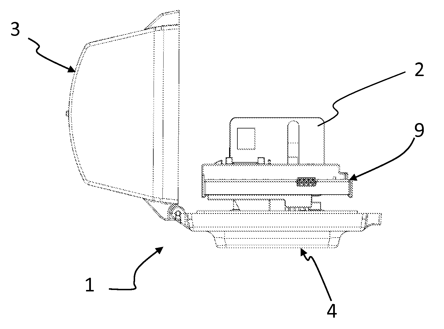
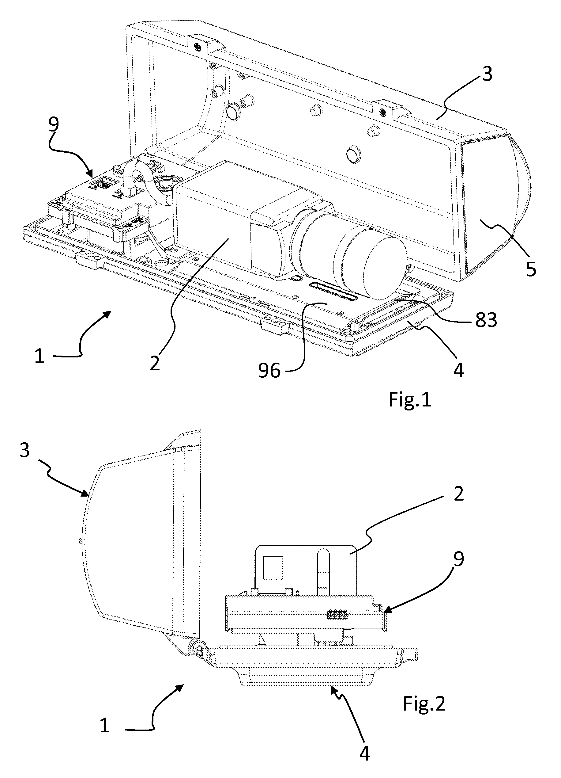
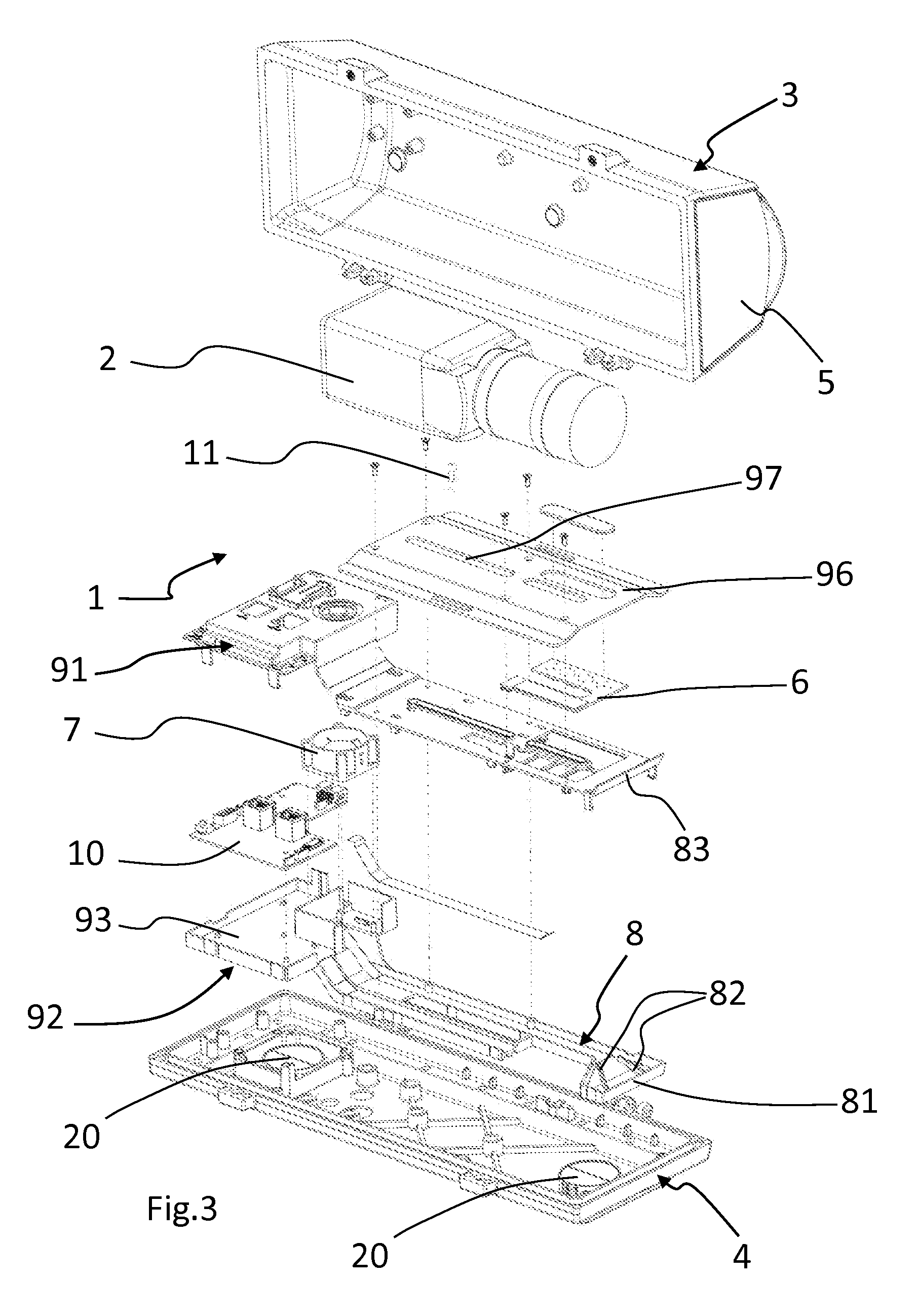
[0034]With reference to the annexed figures, they show a case 1 for surveillance video cameras 2 according to the invention.

[0035]The case 1 comprises a first 3 and a second 4 half-shell connectable to each other to define a volume housing at least one videocamera 2.

[0036]In the example of FIG....


PUM


Abstract

The present invention relates to a case (1) for surveillance video cameras (2) comprising a first (3) and a second (4) half-shell connectable to each other to define a housing volume for at least one video camera (2). At least one of the first (3) and the second (4) half-shell comprises a transparent panel (5) intended to be placed in front of a lens of the video camera (2). The case further comprises a holding device (9) for the video camera (2) which defines a duct (8) conveying an air flow generated by air flow generating means (7) towards the transparent panel (5). Heating means (6) are provided for heating the generated air flow. At least one section of the conveying duct (8) has insulating walls. The invention relates also to a video camera holding device for use in protection cases.

Description

TECHNICAL FIELD[0001]The present invention relates to the field of cases for surveillance video cameras according to the preamble of claim 1.PRIOR ART[0002]The use of surveillance video cameras is an increasingly developing field; in this field it is known to house video cameras into enclosures or cases which accomplish several functions, such as protecting the video camera against atmospheric agents (especially in case of outdoor video cameras) and protecting the video camera against possible tampering actions.[0003]To this end such cases are often made of metal and have a transparent panel placed in front of the lens of the video camera, such to allow it to properly monitor the areas of interest.[0004]An example of such case is shown in the international patent application WO2010030558 to PELCO Inc. et al. , wherein the metal case houses a pivotable plate-like support upon which the video camera is secured, whose lens faces the front transparent panel.[0005]In these installations ...

Claims


Application Information

Patent Timeline
Patent Type & Authority Patents(United States)
IPC IPC(8): H04N5/225G03B17/55G08B13/196
CPCH04N5/2252G03B17/55G08B13/19619G08B13/19632B08B17/02H04N23/51
Inventor GROTTO, ALESSIOZATTARA, DARIO
Owner VIDEOTEC SPA
Learn More