
Friction fusion fastening system

a fastening system and friction fusion technology, applied in the direction of friction elements, coatings, applications, etc., can solve the problems of inefficient batch process, slow mould bonding, and huge stress on brake pads

Active Publication Date: 2016-07-12
NUCAP IND
View PDF112 Cites 14 Cited by
  • Summary
  • Abstract
  • Description
  • Claims
  • Application Information

AI Technical Summary

Benefits of technology

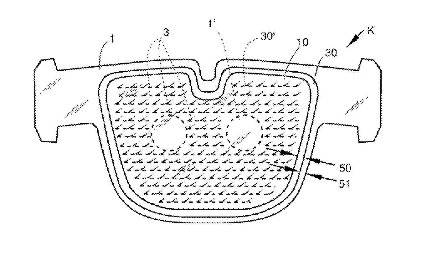
The present invention provides a laminate that includes a base lamina, a second lamina, and a third lamina. The base lamina has multiple barbs raised from its surface, and the second lamina is made of friction material. The third lamina is a sheet of ductile material with multiple barbs raised from both its upper and lower surfaces. The barbs have a flat distal end that overhangs the shank of the barb. The laminate may be used as a brake backing plate or a brake pad. The adhesive used to bond the layers together may be a phenolic resin adhesive or vulcanized rubber. The laminate provides improved adhesion and durability.

Problems solved by technology

Brake pads are subject to enormous stress.
High shear forces combine with extreme range of temperature, and, severe environmental exposure.
Mould-bonding is a slow, inefficient batch process where friction powder is compressed onto bare steel backing plates set in moulds.
During braking, especially with a heavy and / or fast moving vehicle, the hydraulic caliper squeezes the brake disc with the brake pads resulting in frictional drag that generates high temperatures and high shear forces at the bond line.
Over time, moisture reaches the bare steel which begins rusting.
The rust, in turn, progressively weakens the bond line which can lead to partial or full delamination, a highly dangerous condition.
An electro-plated or otherwise protectively coated steel backing plate is not suitable for the mould-bonding process because the process requires a clean, bare steel surface.
However, the holes led to fracturing-crumbling-spalling of the pad, escalating with wear.
If rivet heads wore off, the unsecured friction made for dangerous conditions.
As a result rivets have largely been replaced by the above described mould-bonded brake pad and its aforementioned rust problem.

Method used


Image

  • Friction fusion fastening system
  • Friction fusion fastening system
  • Friction fusion fastening system

Examples


first embodiment

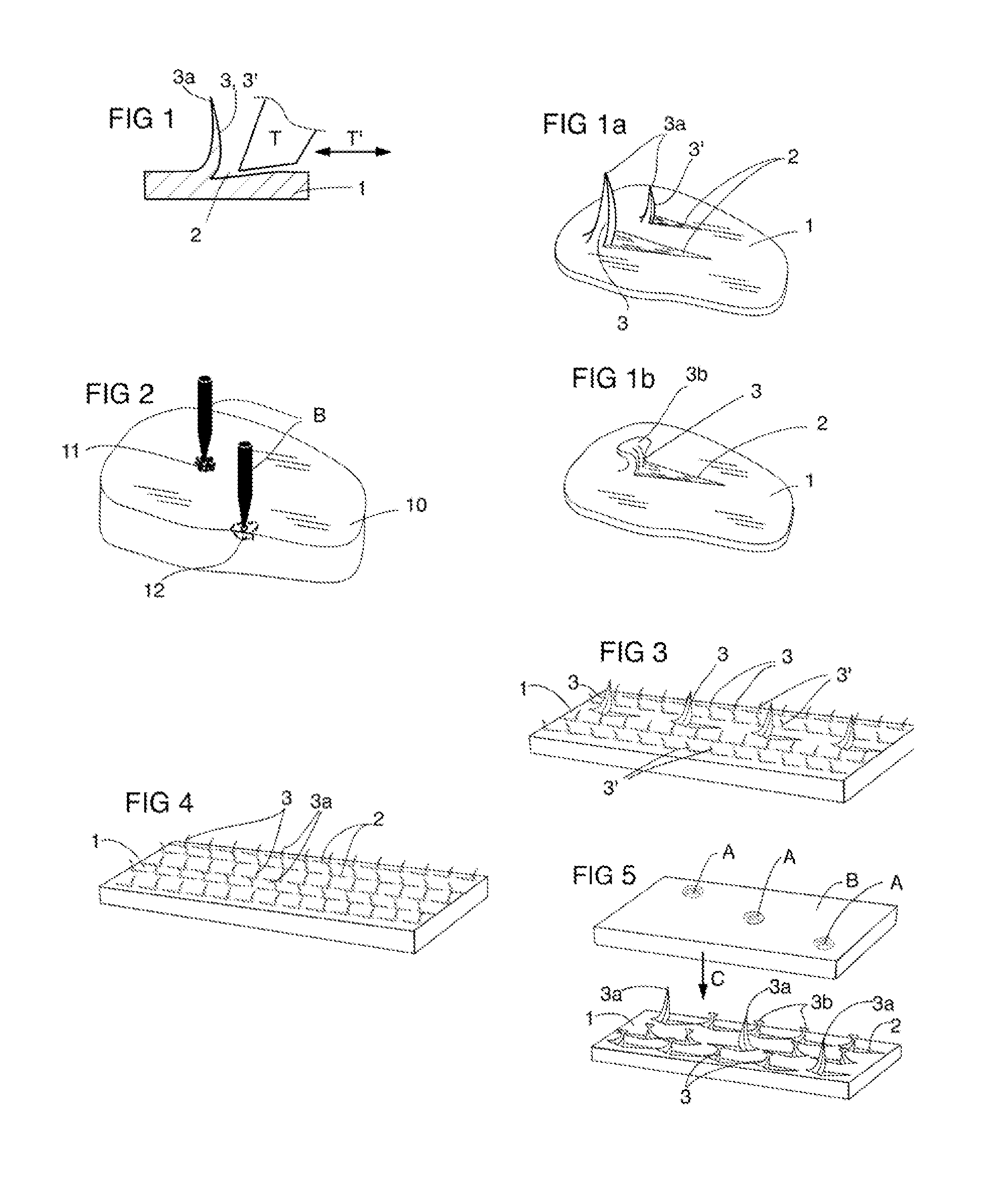
[0054]In a first embodiment, the barbed backing plate has fewer tall barbs distributed amongst many short barbs. The two laminae are pressed together such that the long pointed barbs pierce into the surface, the friable material lamina coming to rest on the shorter barbs about and under which the adhesive flows and hardens.

second embodiment

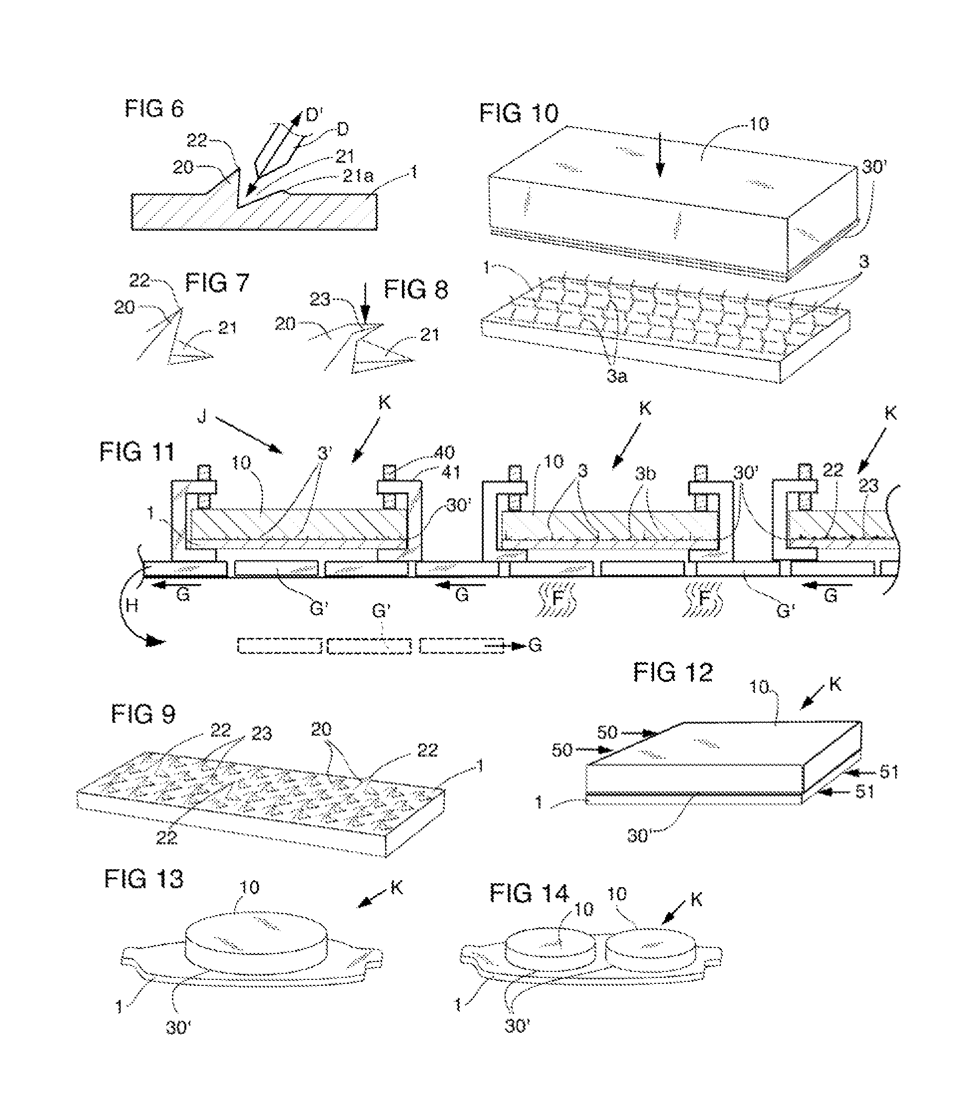
[0055]In a second embodiment, all of the barbs are initially tall and pointed. Then, a pressure plate with spaced holes presses down onto the array of barbs, heading most of them. Stop blocks for the pressure plate ensure the array of heads are all of the same height thereby creating a plane of heads parallel to the plate. Those barbs that enter the plate's holes are unaffected and so remain tall and pointed. As before the two laminae are pressed together with an adhesive between them such that the long barbs pierce at least some distance into the friction material as it comes to rest on the headed barbs about which the adhesive flows and hardens.

third embodiment

[0056]In a third embodiment, all the barbs on the plate are small, short and pointed such that they all pierce, but only to a small diameter and depth that precludes fracturing. Adhesive again fills the gaps and interstices.


PUM

PropertyMeasurementUnit
ductileaaaaaaaaaa
heightaaaaaaaaaa
heightsaaaaaaaaaa

Abstract

A laminate comprises a first ductile material textured with barbs and a second friable material. First material is preferably electro-plated steel. Second material may be a brake friction composition. Barbs may be pointed or headed or in combination. Second material may be in the form of castings, sheets or pads. Second material may be impaled by at least some of the barbs. Lamination of first and second materials preferably includes an adhesive therebetween. The adhesive may include uncured rubber to be vulcanized in place.

Description

FIELD OF THE INVENTION[0001]Laminates comprising friable material laminated to ductile material such as brake pads and shoes, and lamination methods thereof.BACKGROUND OF THE INVENTION[0002]Disc brake pads are an example of a laminate where a friable pad of friction material is bonded to a backing plate of ductile steel. The plate lamina backs the friable friction lamina, preventing it from cracking or fracturing. Concrete, cement, gypsum board and the like are examples of friable materials that may likewise be laminated to more ductile materials. In this disclosure, the brake pad will be used as the exemplary laminate.[0003]Brake pads are subject to enormous stress. High shear forces combine with extreme range of temperature, and, severe environmental exposure. Yet they are fundamental to safe vehicle operation.[0004]By way of background, today's brake pads are mould-bonded where a mixture of assorted powdered minerals and resins along with organic and metallic fibres is compressed...

Claims


Application Information

Patent Timeline
Patent Type & Authority Patents(United States)
IPC IPC(8): F16D65/00B32B3/30B32B7/12B32B15/04F16D69/04
CPCF16D69/04B32B3/30B32B7/12B32B15/04F16D2069/0441F16D2069/0466B32B2475/00B32B2255/06B32B2255/26B32B15/06B32B15/18B32B25/02B32B25/04B32B27/42B32B2307/714B32B2307/744B32B2437/02B32B2605/00B21J5/068F16D65/04A43B1/00
Inventor ARBESMAN, RAYMACKELVIE, WINSTON
Owner NUCAP IND
Learn More