Sensor heat shield structure for a vehicle exhaust system

a technology of heat shield structure and vehicle exhaust, which is applied in the direction of exhaust treatment, machines/engines, mechanical equipment, etc., can solve the problems of affecting the effect of body work, requiring special attention, and often plastic body work

Active Publication Date: 2016-07-05
HONDA MOTOR CO LTD
View PDF30 Cites 10 Cited by
  • Summary
  • Abstract
  • Description
  • Claims
  • Application Information

AI Technical Summary

Benefits of technology

[0003]In accordance with one aspect, an exhaust system for a vehicle comprises an exhaust pipe having an outer surface. A heat insulating cover is mounted to the exhaust pipe and configured to at least partially surround the outer surface of the exhaust pipe. The heat insulating cover includes a body having a planar section defining a surface area. The planar section has an inner surface spaced from the outer surface of the exhaust pipe to define a gap there between. A mounting boss is provided in the gap and is in direct contact with the inner surface of the planar section. An exhaust constituent sensor is releasably mounted to the exhaust pipe. A distal end portion of the exhaust constituent sensor is received in the mounting boss and projects through an opening in the outer surface of the exhaust pipe and into a passage of the exhaust pipe. The direct contact of the mounting boss with the inner surface of the planar section forms a mechanical seal preventing high temperature air from around the exhaust pipe from flowing toward a proximal end portion of the exhaust constituent sensor.
[0005]In accordance with yet another aspect, an exhaust system for a vehicle comprises a heat insulating cover mounted to an exhaust pipe. A mounting boss is located between an inner surface of the cover and an outer surface of the exhaust pipe. The mounting boss includes a first end portion having an annular flange in direct contact with the inner surface of the cover and a second end portion dimensioned to be received in an opening located in the outer surface of the exhaust pipe. An exhaust constituent sensor is mounted directly to the mounting boss. A surface of the annular flange in direct contact with the inner surface of the heat insulating cover extends parallel to the inner surface to define a continuous metal to metal contact such that the annular flange prevents a flow of high temperature air generated by the exhaust system toward the exhaust constituent sensor. The annular flange further transfers heat generated by the exhaust pipe by conduction to the heat insulating cover. The heat insulating cover acts as a heat sink absorbing and dissipating the transferred heat into an associated surrounding environment.

Problems solved by technology

Furthermore, the body work is often plastic and requires special attention to dissipation of the heat generated by the exhaust system.
At the other end of the oxygen sensor are wires insulated with a plastic coating which can be adversely affected by the high temperatures generated by the exhaust system.

Method used


Image

  • Sensor heat shield structure for a vehicle exhaust system
  • Sensor heat shield structure for a vehicle exhaust system
  • Sensor heat shield structure for a vehicle exhaust system

Examples


Embodiment Construction

[0013]It should, of course, be understood that the description and drawings herein are merely illustrative and that various modifications and changes can be made in the structures disclosed without departing from the present disclosure. In general, the figures of the exemplary exhaust sensor heat shield structure are not to scale. It will also be appreciated that the various identified components of the exemplary sensor heat shield structure disclosed herein are merely terms of art that may vary from one manufacturer to another and should not be deemed to limit the present disclosure.

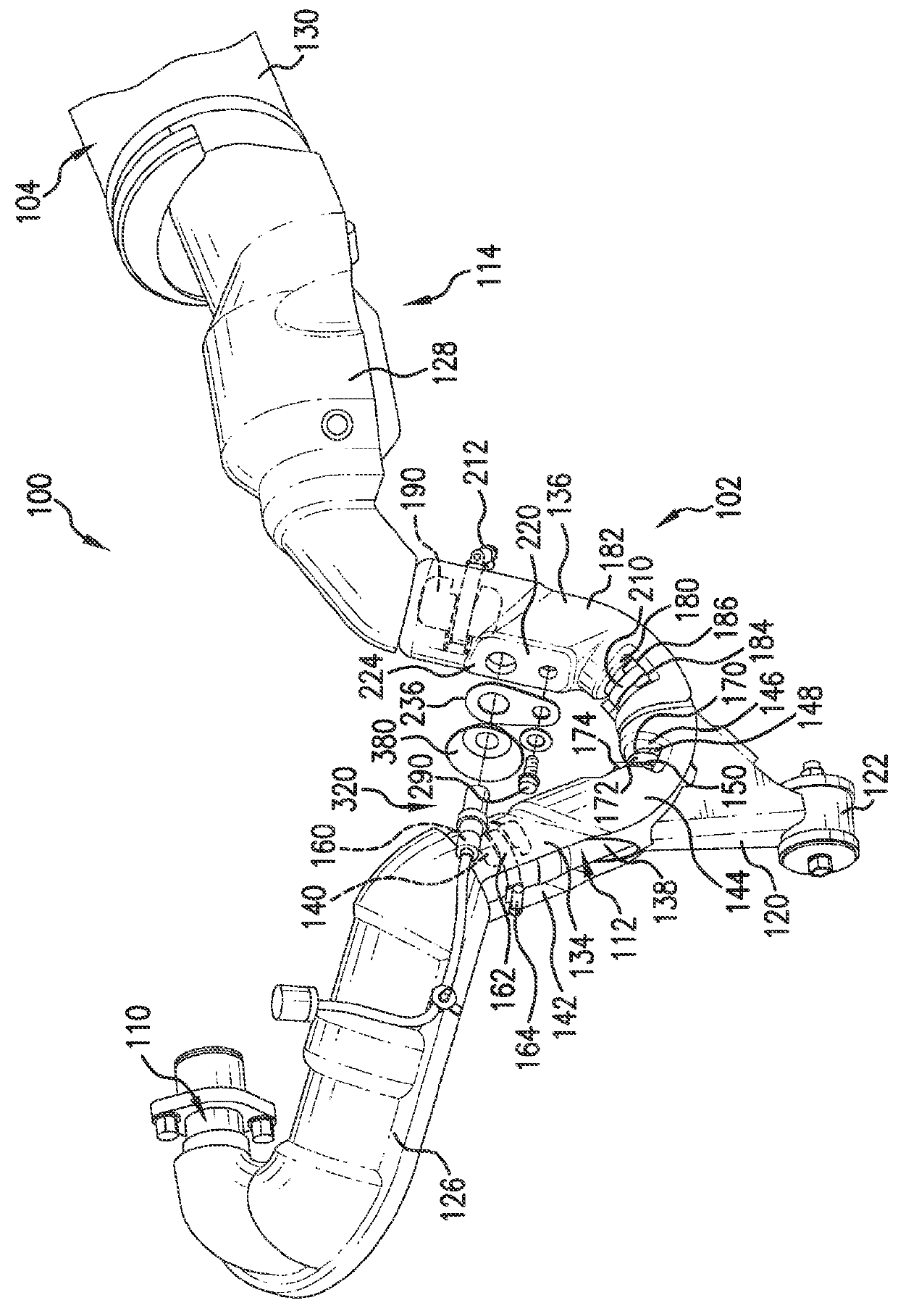
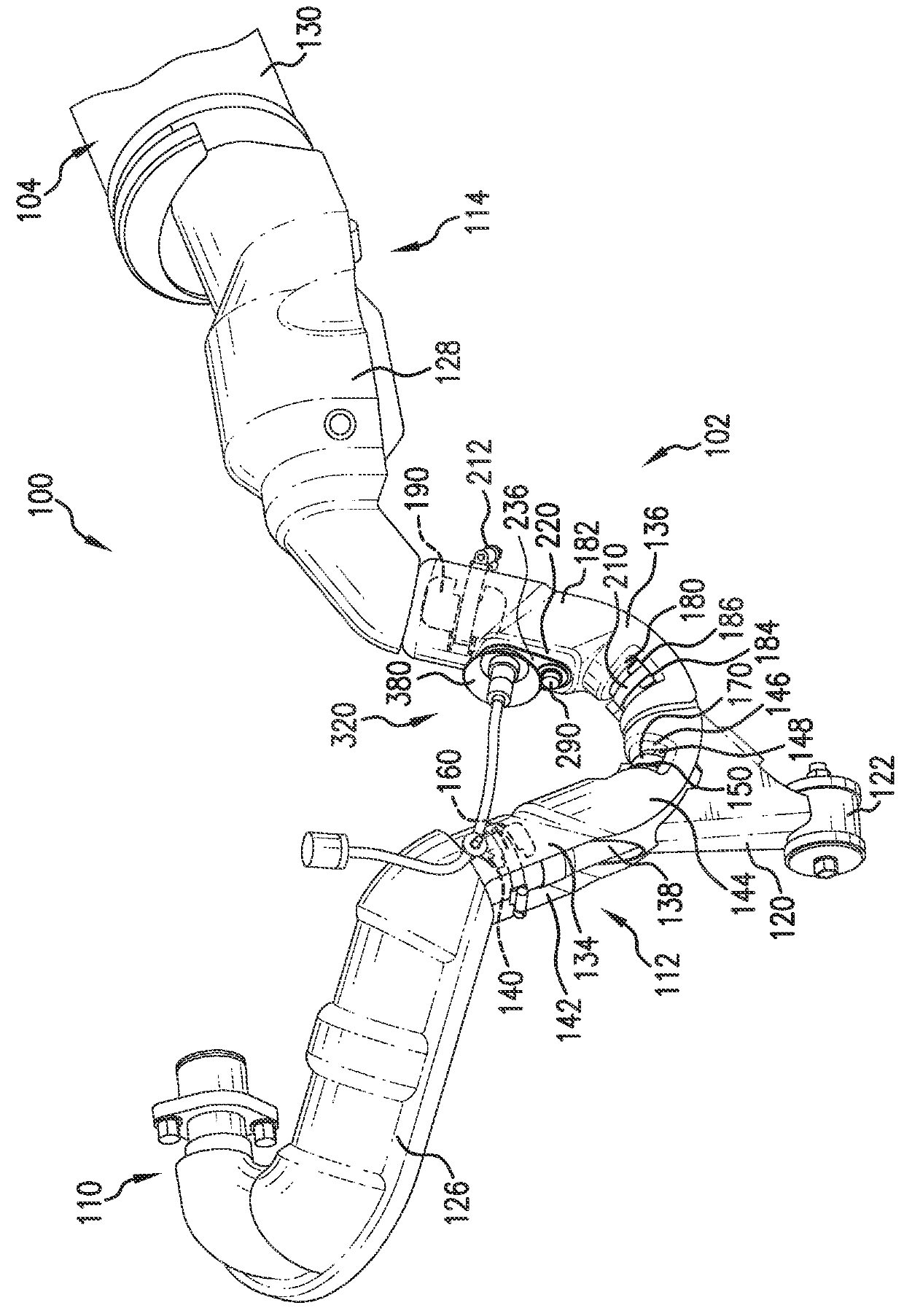
[0014]Referring now to the drawings, wherein like numerals refer to like parts throughout the several views, FIGS. 1 and 2 illustrate an exhaust system 100 for a vehicle, such as, for example, an off road recreational vehicle, according to the present disclosure. The exhaust system 100 includes an exhaust unit 102 configured to be connected at an upstream end to a vehicle engine (not shown) and at a dow...


PUM


Abstract

An exhaust system includes an exhaust pipe and a heat insulating cover surrounding an outer surface of the exhaust pipe. The cover includes a planar section defining a surface area. An inner surface of the planar section is spaced from the outer surface to define a gap there between. A separate reinforcement is mounted to the planar section. A mounting boss provided in the gap is in direct contact with the inner surface. An exhaust constituent sensor is mounted to the exhaust pipe. A distal end portion of the sensor is received in the mounting boss and projects through an opening in the outer surface and into an exhaust passage. The direct contact of the mounting boss with the inner surface forms a mechanical seal preventing high temperature air from around the exhaust pipe from flowing toward a proximal end portion of the sensor.

Description

BACKGROUND[0001]Exhaust constituent sensors have been used for many years in vehicles to sense the presence of constituents in exhaust gasses (e.g., oxygen, hydrocarbons, nitrous oxides) and to sense, for example, when an exhaust gas content switches from rich to lean or lean to rich. Because exhaust constituent sensors are mounted to components of the vehicle exhaust flow system, the sensors must be durable and the sensors must be able to operate in a high temperature environment without being damaged by exposure to such high temperatures. The exhaust constituent sensors are typically installed in an exhaust pipe which is part of the vehicle's exhaust flow system and more specifically, the exhaust constituent responsive end of the sensor is disposed within an opening in the exhaust pipe so that exhaust gasses flow into the sensor and the level of the exhaust constituent to be sensed is communicated to a control system of the vehicle.[0002]Due to the ramping up of emissions regulati...

Claims


Application Information

Patent Timeline
Patent Type & Authority Patents(United States)
IPC IPC(8): F01N3/02F01N13/00F01N13/14
CPCF01N13/008F01N13/14F01N2260/20
Inventor BOWERS, LEE N.
Owner HONDA MOTOR CO LTD
Why Eureka
Try Eureka