
Power adaptation avoidance during crosstalk measurements

a crosstalk measurement and power adaptation technology, applied in the field of access nodes and methods, can solve the problems of limited crosstalk cancellation performances, line is unable to adapt itself, risk of errors, etc., and achieve the effect of improving crosstalk estimation and vectoring performances and ensuring line stability

Active Publication Date: 2016-06-21
RPX CORP
View PDF12 Cites 0 Cited by
  • Summary
  • Abstract
  • Description
  • Claims
  • Application Information

AI Technical Summary

Benefits of technology

[0031]It is an object of the present invention to improve crosstalk estimation and vectoring performances over a loop plant, while guaranteeing line stability.
[0047]This embodiment is advantageous as it avoids the CPE repeating incessantly the power adaptation command during the crosstalk measurement phase: the CPE is rather requested to wait for a certain time value to expire before issuing again the power adaptation command. The time value is determined according to the current remaining time till the completion of the on-going crosstalk measurements.
[0049]This embodiment proactively prevents the CPE from issuing any power control command while crosstalk measurements are on-going by issuing a suspend signal at the beginning of the crosstalk measurement phase.

Problems solved by technology

Crosstalk (or inter-channel interference) is a major source of channel impairment for Multiple Input Multiple Output (MIMO) communication systems, such as Digital Subscriber Line (DSL) communication systems.
Yet, limited vectoring capabilities and / or specific network topologies may prevent such an exhaustive approach, in which case the vectoring group would include a subset only of all the interacting lines, thereby yielding limited crosstalk cancellation performances.
This means that the line is unable to adapt itself to new noise conditions: if noise increases (e.g., RFI, residual crosstalk), there is a risk for errors, meaning a risk for line retrain.
Clearly, this may be too costly for a large vectoring system.

Method used


Image

  • Power adaptation avoidance during crosstalk measurements
  • Power adaptation avoidance during crosstalk measurements
  • Power adaptation avoidance during crosstalk measurements

Examples


Embodiment Construction

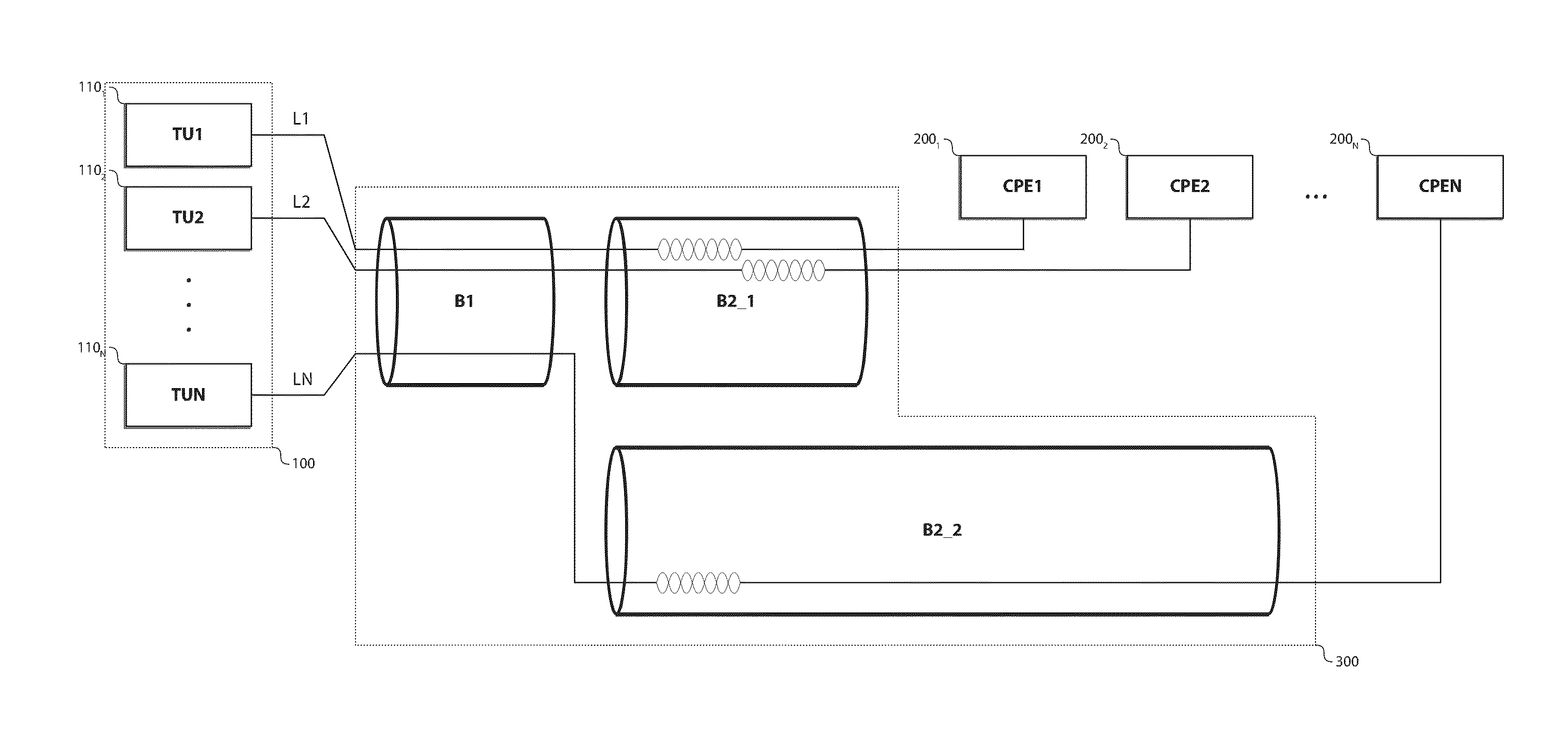
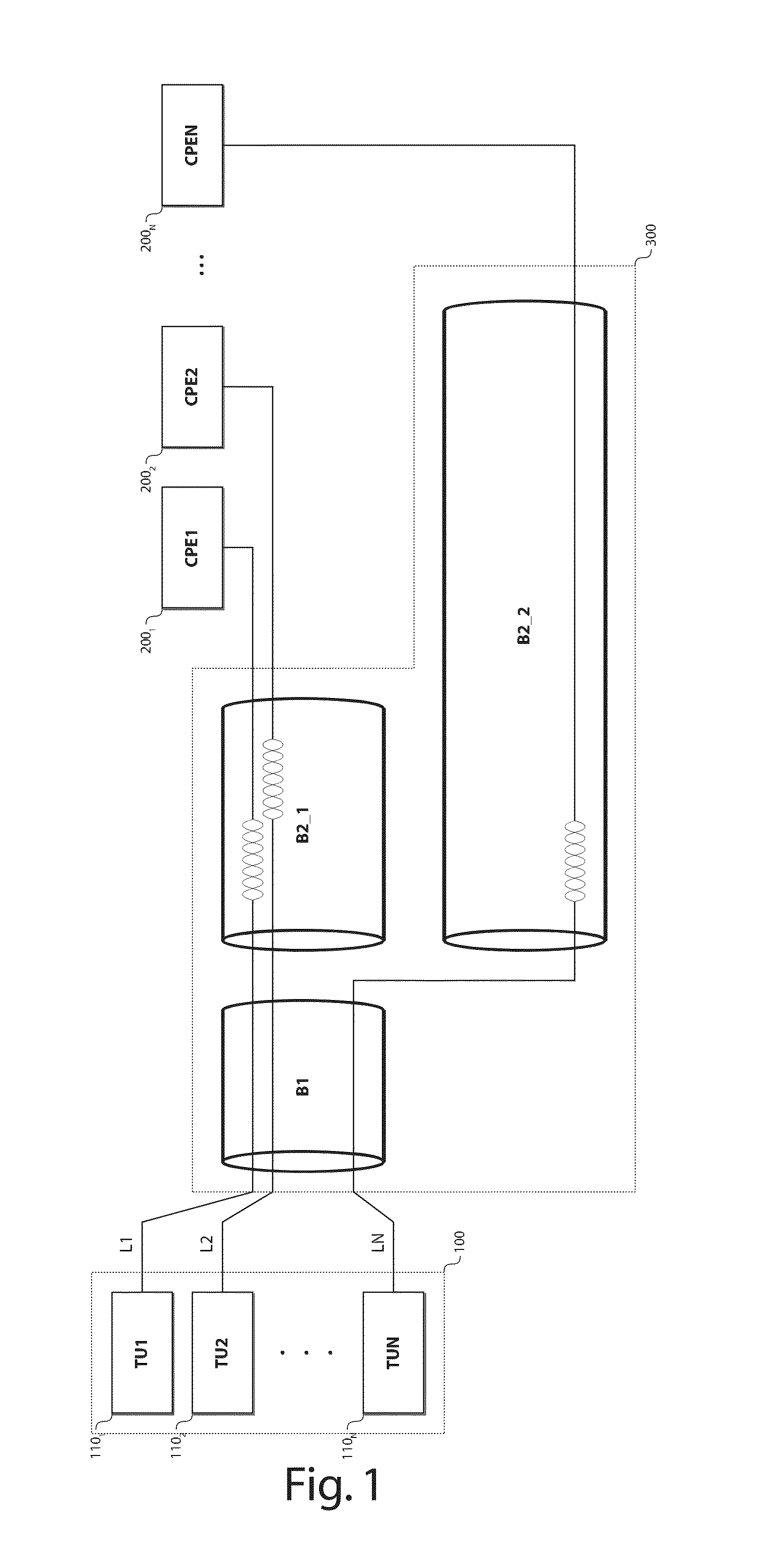
[0061]There is seen in FIG. 1 a DSL communication system 1 for providing broadband access to subscribers.

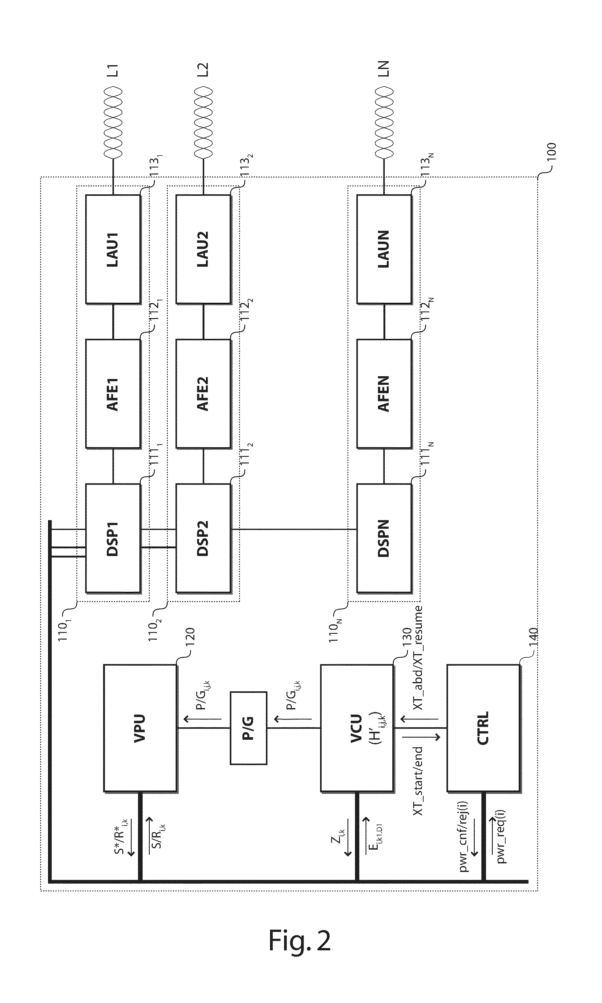
[0062]The DSL communication system 1 comprises a loop plant 300, a DSLAM 100 and N CPEs 2001 to 200N (or CPE1 to CPEN). The DSLAM 100 comprises N transceivers 1101 to 110N (or TU1 to TUN) coupled via N subscriber lines L1 to LN to respective ones of the N CPEs 2001 to 200N. The subscriber lines L1 to LN are for example Unshielded Twisted Pairs (UTP).

[0063]The subscriber lines L1 to LN are bundled together within one or more binders B1, B2_1 and B2_2, and induce crosstalk into each other as they are in close vicinity over whole or part of their length. The subscriber lines L1 to LN are assumed to form part of the same vectoring group.

[0064]Because downstream and upstream communications are assigned different and non-overlapping frequency bands—Frequency Division Duplexing (FDD)—, crosstalk mostly reduces to Far-End Crosstalk (FEXT): some substantial amount of the signal transmitte...


PUM


Abstract

In one embodiment, the access node includes a vectoring control unit for estimating crosstalk coefficients between a set of subscriber lines based on crosstalk measurements carried out over the set of subscriber lines during a crosstalk measurement phase, and a vectoring processing unit for jointly processing, for crosstalk mitigation, signals to be transmitted over, or received from, the set of subscriber lines based on the estimated crosstalk coefficients. The access node further includes a controller configured to either postpone the execution of power adaptation over a particular line out of the set of subscriber lines after the completion of the crosstalk measurement phase, or to postpone the crosstalk measurement phase after the completion of power adaptation over the particular line.

Description

[0001]This application is the national phase under 35 U.S.C. §371 of PCT International Application No. PCT / EP2012 / 066603 which has an International filing date of Aug. 27, 2012, which claims priority to European patent application number EP 11306208.7 filed Sep. 23, 2011; the entire contents of each of which are hereby incorporated by reference.TECHNICAL FIELD OF THE INVENTION[0002]The present invention relates to an access node and method for connecting subscriber devices through a loop plant.TECHNICAL BACKGROUND OF THE INVENTION[0003]Crosstalk (or inter-channel interference) is a major source of channel impairment for Multiple Input Multiple Output (MIMO) communication systems, such as Digital Subscriber Line (DSL) communication systems.[0004]As the demand for higher data rates increases, DSL systems are evolving toward higher frequency bands, wherein crosstalk between neighboring transmission lines (that is to say, transmission lines that are in close vicinity such as twisted cop...

Claims


Application Information

Patent Timeline
Patent Type & Authority Patents(United States)
IPC IPC(8): H04L25/03H04B3/34H04M3/34H04L27/26H04L25/08H04B3/487
CPCH04L25/03305H04B3/487H04L25/0328H04L25/085H04L27/2691H04M3/34
Inventor VERLINDEN, JANVANDERHAEGEN, DIRK
Owner RPX CORP
Learn More