
Triple-band antenna and method of manufacture

a technology of tri-band antennas and antennas, applied in the direction of individual energised antenna arrays, resonant antennas, substantially flat resonant elements, etc., can solve the problems of unable to support a 60 ghz band using a conventional dipole antenna, limited area for installing additional circuitry,

Active Publication Date: 2016-06-14
QUALCOMM INC
View PDF26 Cites 6 Cited by
  • Summary
  • Abstract
  • Description
  • Claims
  • Application Information

AI Technical Summary

Benefits of technology

This patent describes a triple-band antenna that can transmit and receive signals in three different frequency bands. The antenna includes a printed antenna with two wings that transmit and receive low-frequency signals, and a printed antenna array with multiple radiating elements that transmit and receive high-frequency signals. The antenna array is grounded using one of the wings. The method of manufacturing the triple-band antenna involves printing the dipole antenna, connecting a feed wire to the wings, suspending a plurality of radiating elements over one of the wings, connecting each radiating element to a second feed wire and an RFIC high-frequency band transceiver, grounding each second feed wire to the wing, and mounting the structure on an insulated board. The technical effect of this patent is the development of a multi-band antenna that can transmit and receive signals in three different frequency bands.

Problems solved by technology

The physical size of such devices is relatively small, thus the area for installing additional circuitry to support 60 GHz applications is limited.
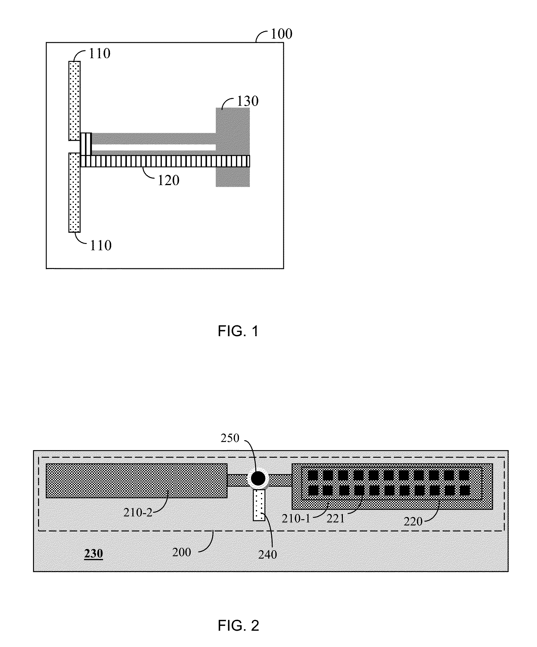
Trying to support a 60 GHz band using a conventional dipole antenna, such as shown in FIG. 1, is not feasible as the antenna gain would be too low in order to enable efficient transmission and reception of radio frequency signals.

Method used


Image

  • Triple-band antenna and method of manufacture
  • Triple-band antenna and method of manufacture
  • Triple-band antenna and method of manufacture

Examples


Embodiment Construction

[0016]The embodiments disclosed by the invention are only examples of the many possible advantageous uses and implementations of the innovative teachings presented herein. In general, statements made in the specification of the present application do not necessarily limit any of the various claimed inventions. Moreover, some statements may apply to some inventive features but not to others. In general, unless otherwise indicated, singular elements may be in plural and vice versa with no loss of generality. In the drawings, like numerals refer to like parts through several views.

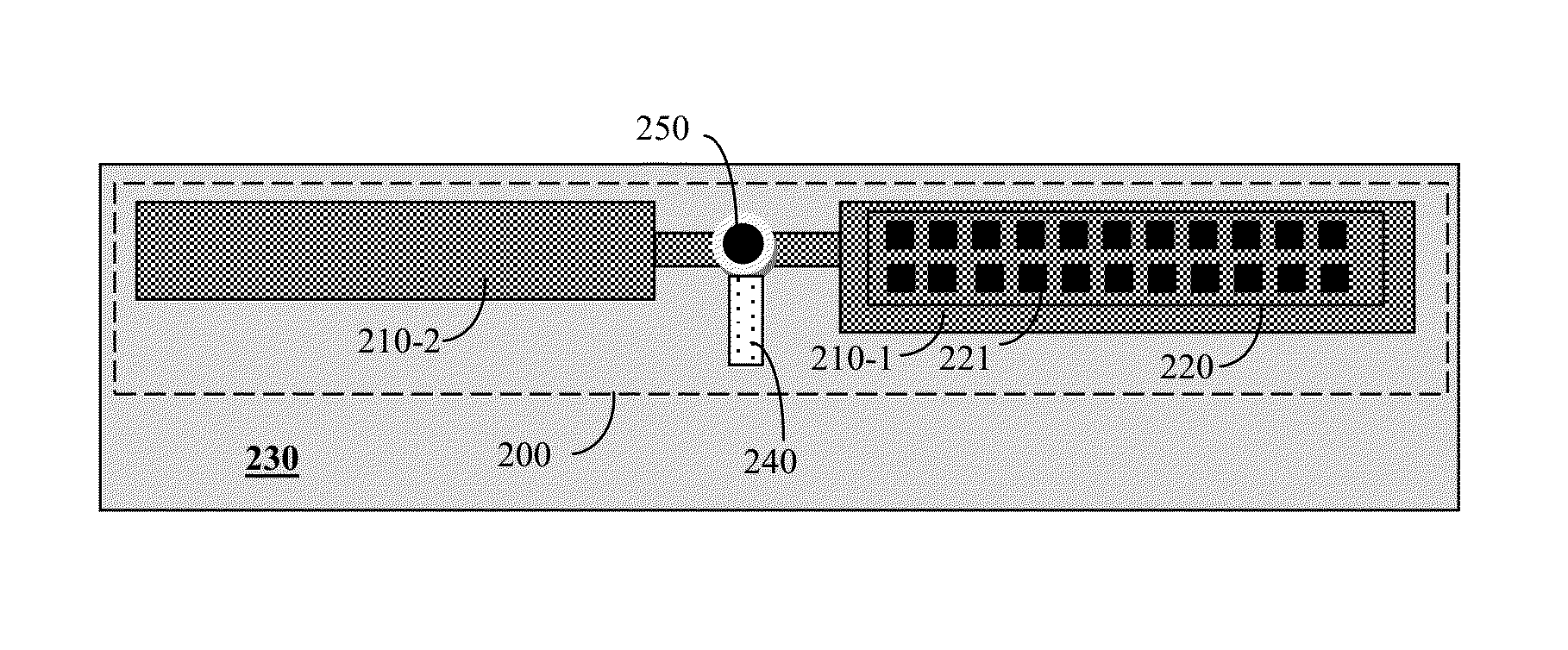
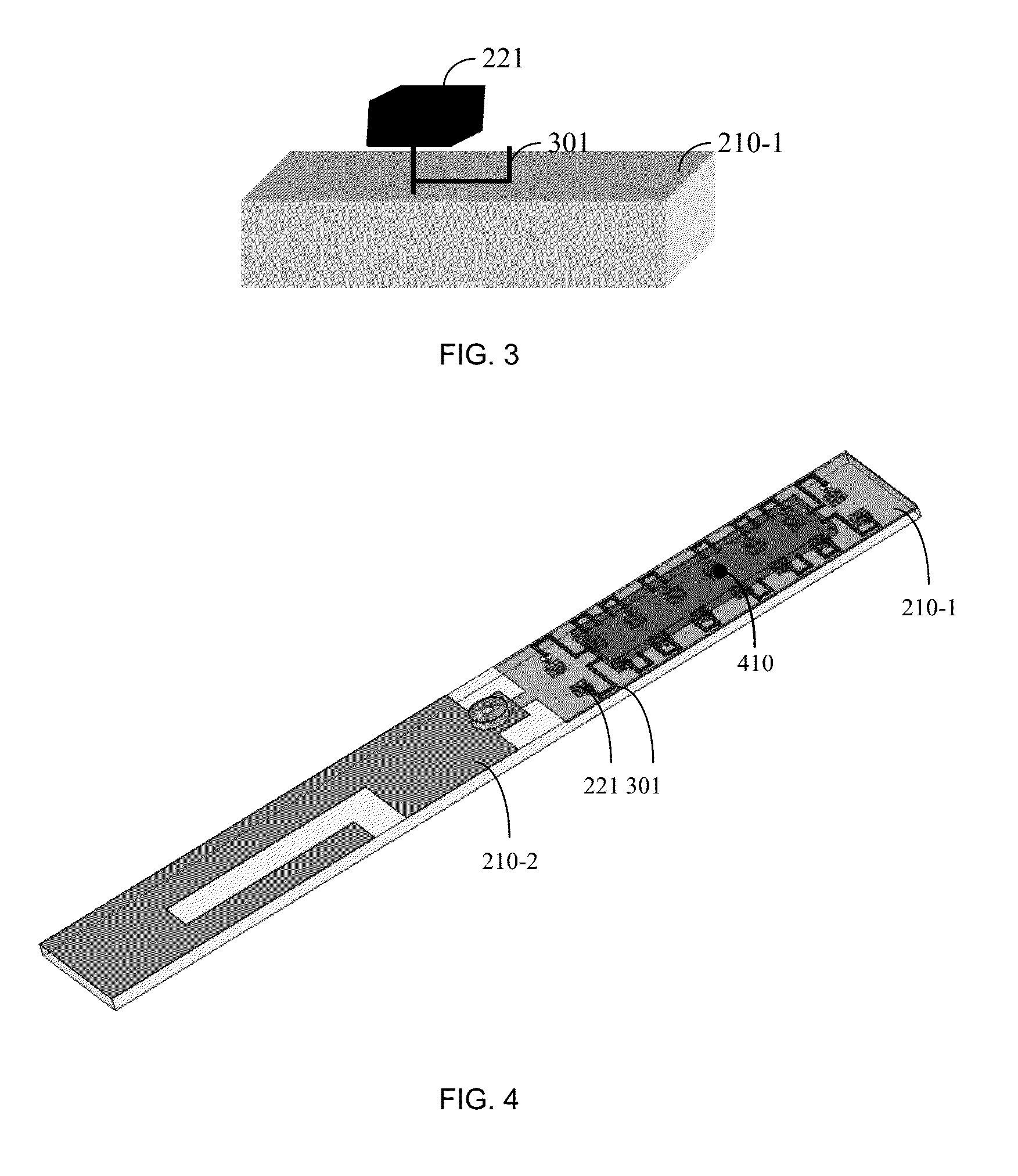
[0017]FIG. 2 shows a schematic diagram of a triple-band antenna 200 constructed in accordance with an embodiment of the invention. The antenna 200 is designed to receive and transmit radio frequency (RF) signals at three different frequency bands. In accordance with an embodiment of the invention, these bands include, but are not limited to 60 GHz, 2.4 GHz, and 5 GHz, thereby supporting applications in both t...


PUM

PropertyMeasurementUnit
frequencyaaaaaaaaaa
frequencyaaaaaaaaaa
frequencyaaaaaaaaaa

Abstract

A triple-band antenna for transmitting and receiving low-frequency band signals and high-frequency band signals. The triple-band antenna includes a printed antenna having two wings for transmitting and receiving low-frequency signals; and an antenna array including a plurality of radiating elements being printed on one of the wings of the printed antenna, wherein the antenna array transmits and receives the high-frequency band signals, wherein one of the wings of the printed dipole is a ground for the antenna array.

Description

CROSS-REFERENCE TO RELATED APPLICATIONS[0001]This application claims the benefit of U.S. provisional application No. 61 / 333,957 filed on May 12, 2010, the contents of which are herein incorporated by reference.TECHNICAL FIELD[0002]The present invention relates generally to antennas for portable wireless communication devices, and particularly to triple-band antennas.BACKGROUND OF THE INVENTION[0003]The 60 GHz band is an unlicensed band which features a large amount of bandwidth and a large worldwide overlap. The large bandwidth means that a very high volume of information can be transmitted wirelessly. As a result, multiple applications, that require transmission of a large amount of data, can be developed to allow wireless communication around the 60 GHz band. Examples for such applications include, but are not limited to, wireless high definition TV (HDTV), wireless docking station, wireless Gigabit Ethernet, and many others.[0004]The objective of the industry is to integrate 60 G...

Claims


Application Information

Patent Timeline
Patent Type & Authority Patents(United States)
IPC IPC(8): H01Q21/30H01Q21/06H01Q9/04H01Q3/26H01Q1/38H01Q1/24H01Q9/28
CPCH01Q9/285H01Q1/243H01Q1/38H01Q3/26H01Q9/0407H01Q21/065Y10T29/49016H01Q5/35H01Q5/364H01Q5/40
Inventor MYSZNE, JORGEMARKISH, OFER
Owner QUALCOMM INC
Learn More