Eureka AIR delivers breakthrough ideas for toughest innovation challenges, trusted by R&D personnel around the world.

Mobile communication device

a mobile phone and communication device technology, applied in the direction of resonant antennas, radiating element structural forms, antenna supports/mountings, etc., can solve the problem that an antenna of this type is too large to be conveniently used in a small mobile phon

Inactive Publication Date: 2005-09-27
TELEFON AB LM ERICSSON (PUBL)
View PDF22 Cites 69 Cited by
  • Summary
  • Abstract
  • Description
  • Claims
  • Application Information

AI Technical Summary

Benefits of technology

The invention is a triple band antenna for portable communication devices like mobile phones. It can work in three different frequency bands: low, high, and another high. The antenna has two main parts: a first part that works in both high and low frequency bands, and a second part that can be tuned to a separate high frequency band. This allows the phone to work in three different frequency ranges. The invention is not limited to the specific frequency ranges mentioned, and can be used in existing and future frequency ranges as well.

Problems solved by technology

In many mobile telephones using the 900 MHz and 1800 MHz frequency bands, the antenna has separate portions tuned to respective ones of the two frequency bands, since it is not considered feasible to have one and the same portion of the antenna tuned to a frequency band of more than one octave, with a relatively large unused frequency band between the useful frequency bands.
However, an antenna of this type is too large to be used conveniently in a small mobile phone.

Method used


Image

  • Mobile communication device
  • Mobile communication device
  • Mobile communication device

Examples


Embodiment Construction

[0018]The antenna according to the invention is described with reference to its use in a mobile phone. However, the invention is generally applicable to portable radio communication equipment or mobile radio terminals, such as mobile telephones, pagers, communicators, electronic organisers, smartphones, personal digital assistants (PDAs), or the like.

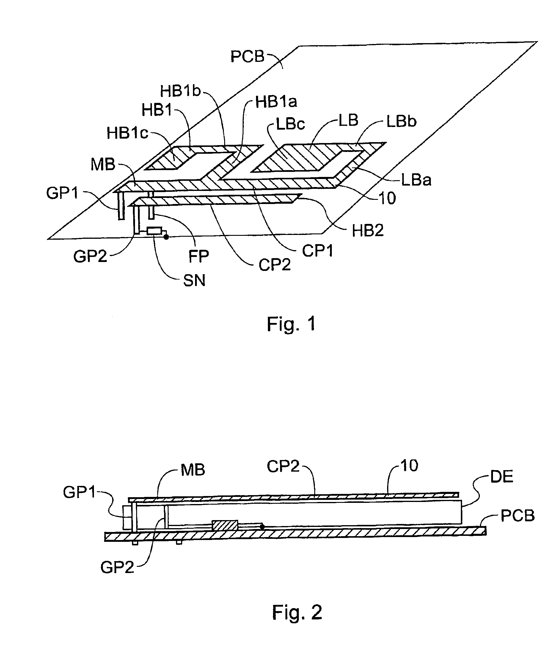
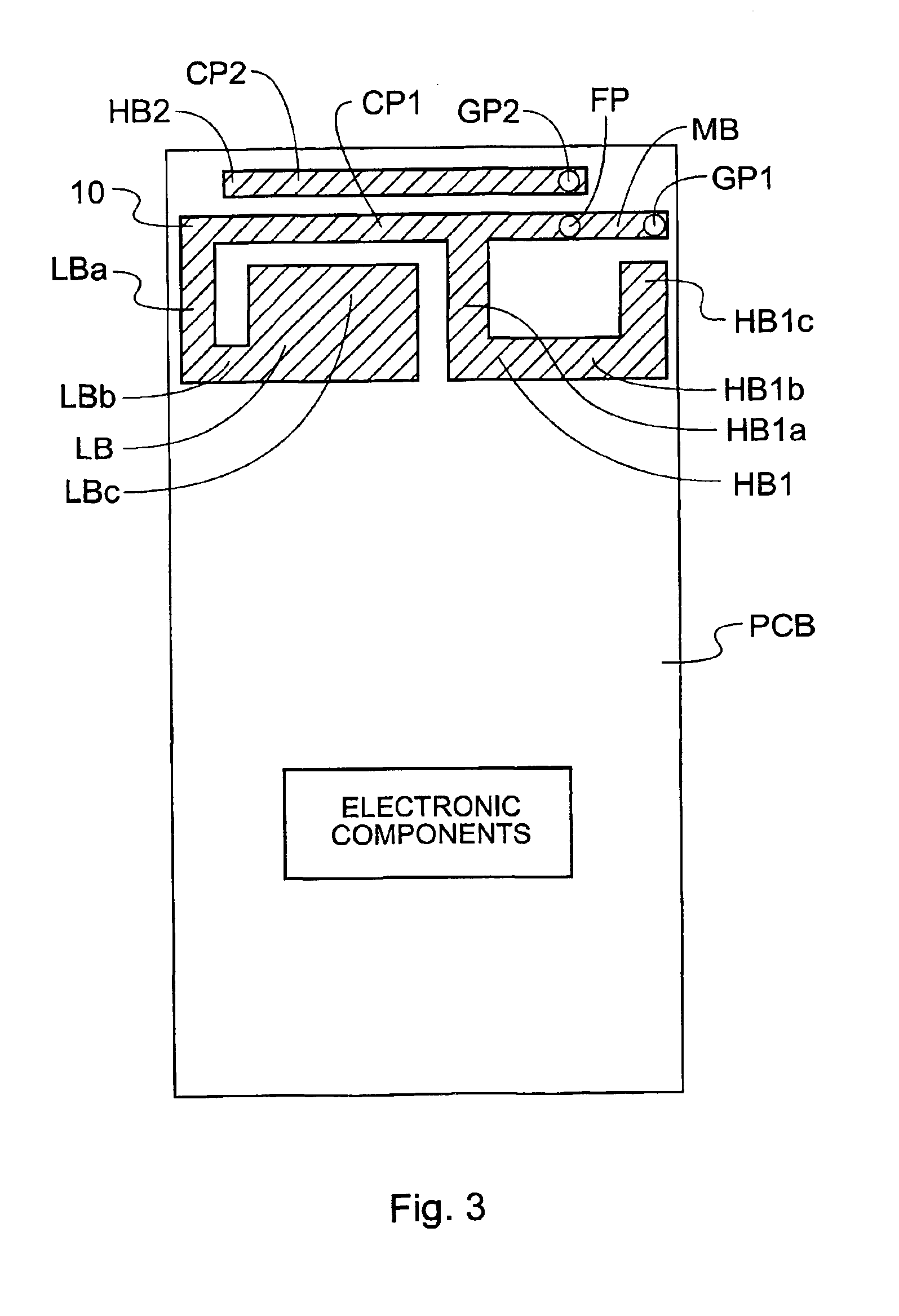
[0019]FIGS. 1-3 show a printed circuit board PCB with an antenna 10 according to the invention, suitable for use in a mobile telephone. In the illustrated embodiment, the printed circuit board has a rectangular shape, but of course the invention is not restricted to the use of a rectangular shape. In practice, the printed circuit board will have a number of electronic components mounted thereon, which are necessary for the operation of the mobile telephone, but which are not part of the invention. In FIG. 3 such components are therefore indicated only schematically.

[0020]In FIGS. 1-3 an electrically conductive material, such as copper, ...


PUM


Abstract

A mobile communications device has a multifrequency band antenna with a low band portion (LB) tuned to a low frequency band, and a first high band portion (HB1) tuned to a first high frequency band at higher frequencies than the low frequency band. The low band portion (LB) and the first high band portion (HB1) have a common first grounding point (GP1), a common feeding point (FP) for feeding input signals to the antenna and for receiving signals from the antenna, and a first conductor portion (CP1), which forms part of the low band portion (LB) and of the first high band portion (HB1). The first conductor portion (CP1) is electrically connected to the first grounding point (GP1) and to the common feeding point (FP). A second high band portion (HB2) is coupled to the first conductor portion (CP1) and tuned to a second high frequency band at a higher frequency than the low frequency band and different from the first high frequency band. A switching network is connected between the second high band portion and ground, allowing the resonant frequency of the second high band portion to be varied, on the basis of a signal which depends on the operating mode of the device, thereby allowing four band operation.

Description

CROSS REFERENCE TO RELATED APPLICATIONS[0001]This application claims the benefit of U.S. Provisional Application No. 60 / 278,751, filed Mar. 27, 2001, which is hereby incorporated herein by reference in its entirety. This application also claims priority under 35 U.S.C. §§ 119 and / or 365 to British Patent Application No. 0107239.6, filed on Mar. 22, 2001; the entire content of which is hereby incorporated by reference.FIELD OF INVENTION[0002]The invention relates to mobile communications devices such as mobile telephones, and in particular to antennas for such devices. Portable communications devices are required to be compact in size, which is a requirement that applies to every component of the devices, including the antenna. Modern mobile telephones use two or more distinct frequency bands, and it is preferable to use the same antenna in all frequency bands used by the telephone.BACKGROUND OF THE INVENTION[0003]Currently, many mobile telephones use one or more of the following thr...

Claims


Application Information

Patent Timeline
Patent Type & Authority Patents(United States)
IPC IPC(8): H01Q5/00H01Q1/38H01Q9/04H01Q19/00H01Q1/24H01Q5/371H01Q5/378
CPCH01Q1/243H01Q1/38H01Q9/0421H01Q5/378H01Q19/005H01Q5/371H01Q9/14H01Q1/24
Inventor YING, ZHINONGH.ANG.KANSSON, KENNETH
Owner TELEFON AB LM ERICSSON (PUBL)
Why Eureka
Eureka Blog
Learn More