
Apparatus and method for generating depth image

a technology of depth image and generating apparatus, which is applied in the direction of instruments, porous material analysis, and using reradiation, etc., can solve the problems of conventional depth camera that may not accurately measure the distance to the object, and the measured distance may often exceed the maximum measurement distance, so as to enhance the maximum measurement distance of a depth, and increase the depth accuracy

Active Publication Date: 2016-06-14
SAMSUNG ELECTRONICS CO LTD
View PDF16 Cites 1 Cited by
  • Summary
  • Abstract
  • Description
  • Claims
  • Application Information

AI Technical Summary

Benefits of technology

[0026]One or more embodiments may include a depth image generating apparatus and method. One or more embodiments of a depth image generating apparatus and method may enhance a maximal measurement distance of a depth more than twice a conventional one, and may enhance an accuracy of the measured depth. One or more embodiments of a depth image generating apparatus may calculate a time taken in a round-trip flight of a light to an object using a change in a quantity of electric charge, and may calculate the depth based on the calculated time and thus, may increase an accuracy of the depth.
[0027]A three-dimensional (3D) image may be restored based on a depth image and a brightness image. The depth image and the brightness image may be generated based on a maximal measurement distance that is extended compared with a conventional one and thus, the 3D image may be more realistic and stereoscopic. The brightness image may be obtained by a general two-dimensional (2D) camera or a 3D camera.

Problems solved by technology

When a conventional depth camera measures a distance, a maximal measurement distance is limited and thus, the measured distance may often exceed the maximal measurement distance.
Therefore, sometimes, the conventional depth camera may not accurately measure a distance to the object due to the limited maximal measurement distance.

Method used


Image

  • Apparatus and method for generating depth image
  • Apparatus and method for generating depth image
  • Apparatus and method for generating depth image

Examples


Embodiment Construction

[0040]Reference will now be made in detail to embodiments, examples of which are illustrated in the accompanying drawings, wherein like reference numerals refer to the like elements throughout. Embodiments are described below to explain the present disclosure by referring to the figures

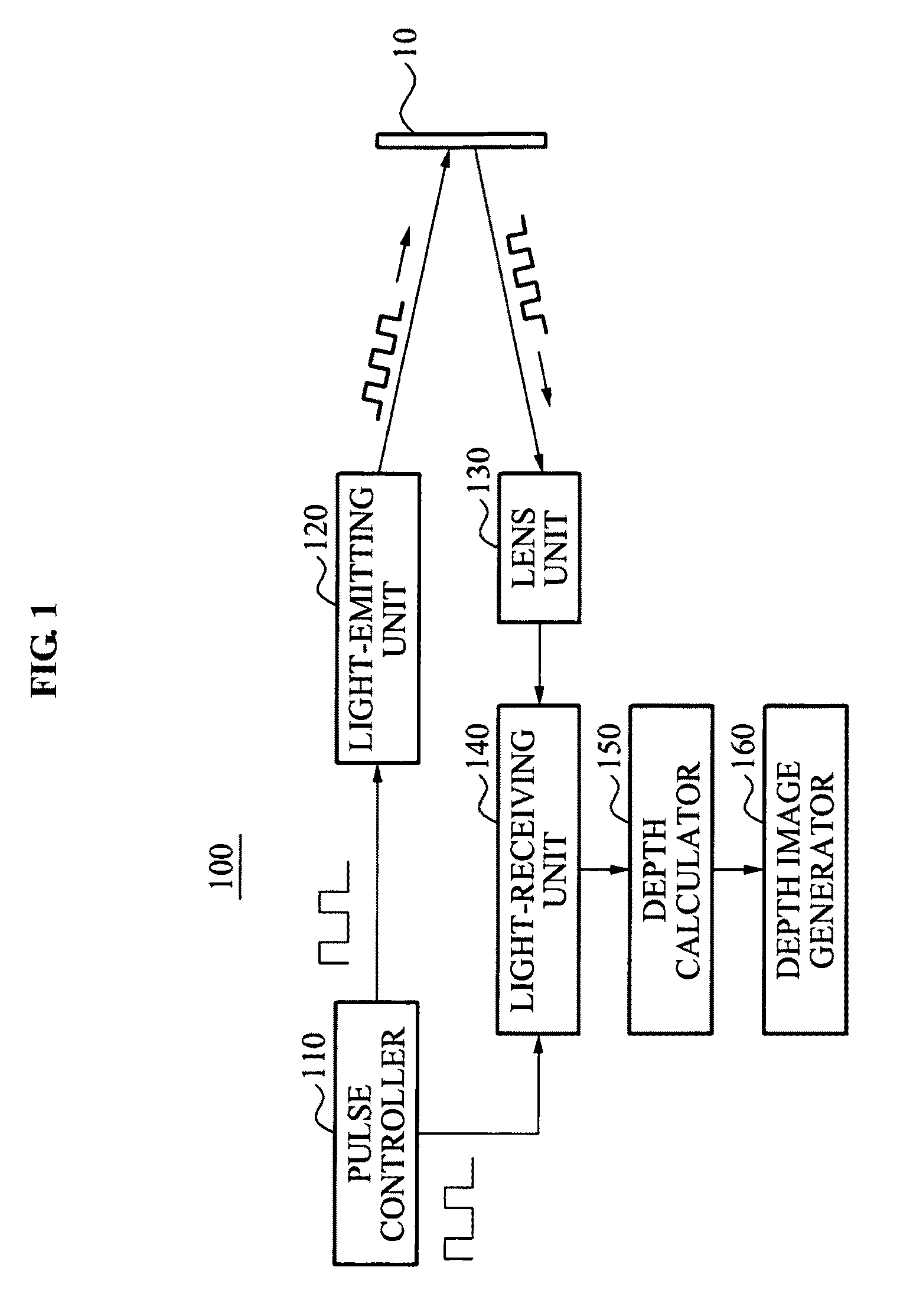
[0041]FIG. 1 illustrates a depth image generating apparatus 100 according to an embodiment.

[0042]Referring to FIG. 1, the depth image generating apparatus 100 may measure a depth of an object 10 based on a time of flight (TOF) scheme, and may generate a depth image to be used for generating a three-dimensional (3D) image of the object 10. The depth-image generating apparatus 100 may be included in a depth camera.

[0043]The depth image generating apparatus 100 may measure a distance to the object 10, namely, a depth of a depth image, based on a pixel unit, using a TOF depth sensor. The depth image generating apparatus 100 may include a pulse controller 110, a light-emitting unit 120, a lens unit 130, a ...


PUM

PropertyMeasurementUnit
speedaaaaaaaaaa
depthaaaaaaaaaa
depthaaaaaaaaaa

Abstract

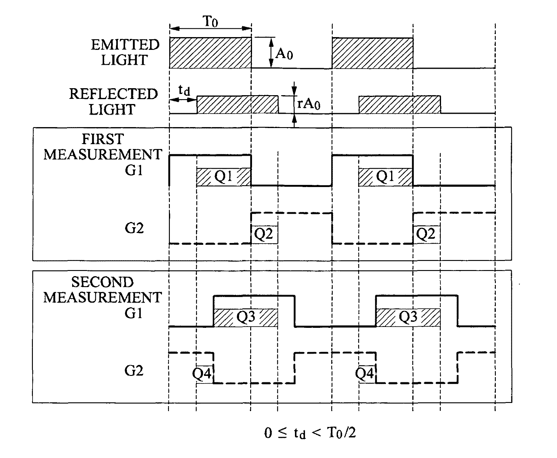
Provided is a depth image generating apparatus and method. The light-receiving unit may include a first gate and a second gate and a depth calculator to calculate a depth based on first light information through fourth light information. The first gate may obtain the first light information from a reflected light of a light emitted based on a first pulse and the second gate may obtain the second light information from a reflected light of a light emitted based on a second pulse, and then the first gate may obtain the third light information from a reflected light of a light emitted based on a third pulse and the second gate may obtain the fourth light information from a reflected light of a light emitted based on a fourth pulse.

Description

CROSS-REFERENCE TO RELATED APPLICATIONS[0001]This application claims the priority benefit of Korean Patent Application No. 10-2010-0060597, filed on Jun. 25, 2010, in the Korean Intellectual Property Office, the disclosure of which is incorporated herein by reference.BACKGROUND[0002]1. Field[0003]Embodiments relate to a depth image generating apparatus and Method, and more particularly, to a depth image generating apparatus and method that may extend a maximal measurement distance of a depth and may maintain an accuracy of the measured depth.[0004]2. Description of the Related Art[0005]A three-dimensional (3D) image may include a color image and a depth image. The depth image may be obtained based on a time of flight (TOF) scheme. An infrared ray-based depth camera may emit an infrared ray to an object, may sense a reflected light from the object, and may measure a TOF to calculate a distance between the camera and the object. The calculated distance may be used as a depth of the de...

Claims


Application Information

Patent Timeline
Patent Type & Authority Patents(United States)
IPC IPC(8): G06K9/00G01N15/06G01S17/10G01S17/89G01S7/486G01S7/4865G01S17/894
CPCG01S17/89G01S17/10G01S7/4865G01S17/894H04N13/128H04N13/254H04N13/271
Inventor KANG, BYONG MINLEE, KEE CHANGKIM, SEONG JIN
Owner SAMSUNG ELECTRONICS CO LTD
Learn More