
Brake device for vehicle and control method thereof

a technology for brake devices and vehicles, applied in brake systems, brake components, transportation and packaging, etc., can solve problems such as inability to sufficiently use regenerative brake force, pulsation of brake fluid, and noise produced by water hammer, and achieve the effect of suppressing the influence of accumulator reaction

Active Publication Date: 2016-05-31
BOSCH CORP
View PDF10 Cites 0 Cited by
  • Summary
  • Abstract
  • Description
  • Claims
  • Application Information

AI Technical Summary

Benefits of technology

The present invention solves the problem of decreased comfort and excessive noise when brake fluid pressure is decreased in conventional vehicles. The invention allows for the use of regenerative brakes while controlling the reaction of the accumulator and securing comfortable brake feel. In addition, the invention reduces noise and vibration when the pump motor operates. The braking force is covered by only the regenerative brakes, and the pressure decreasing valve is opened while the pressure increasing valve is closed to avoid the reaction of the accumulator. This allows for efficient use of regenerative brakes and ensures a comfortable brake feel.

Problems solved by technology

For this reason, even in a case where the braking force can be covered by only the regenerative brake force, there is a case where it is not possible to sufficiently use the regenerative brake force.
At this time, pulsation is produced in the brake fluid, and particularly when a hydraulic difference in the brake fluid is increased at the front and the rear of the pressure decreasing valve, there is concern that noise may be produced by water hammer or the like.

Method used


Image

  • Brake device for vehicle and control method thereof
  • Brake device for vehicle and control method thereof
  • Brake device for vehicle and control method thereof

Examples


Embodiment Construction

[0029]Hereinafter, a preferable embodiment according to the present invention will be described with reference to the drawings.

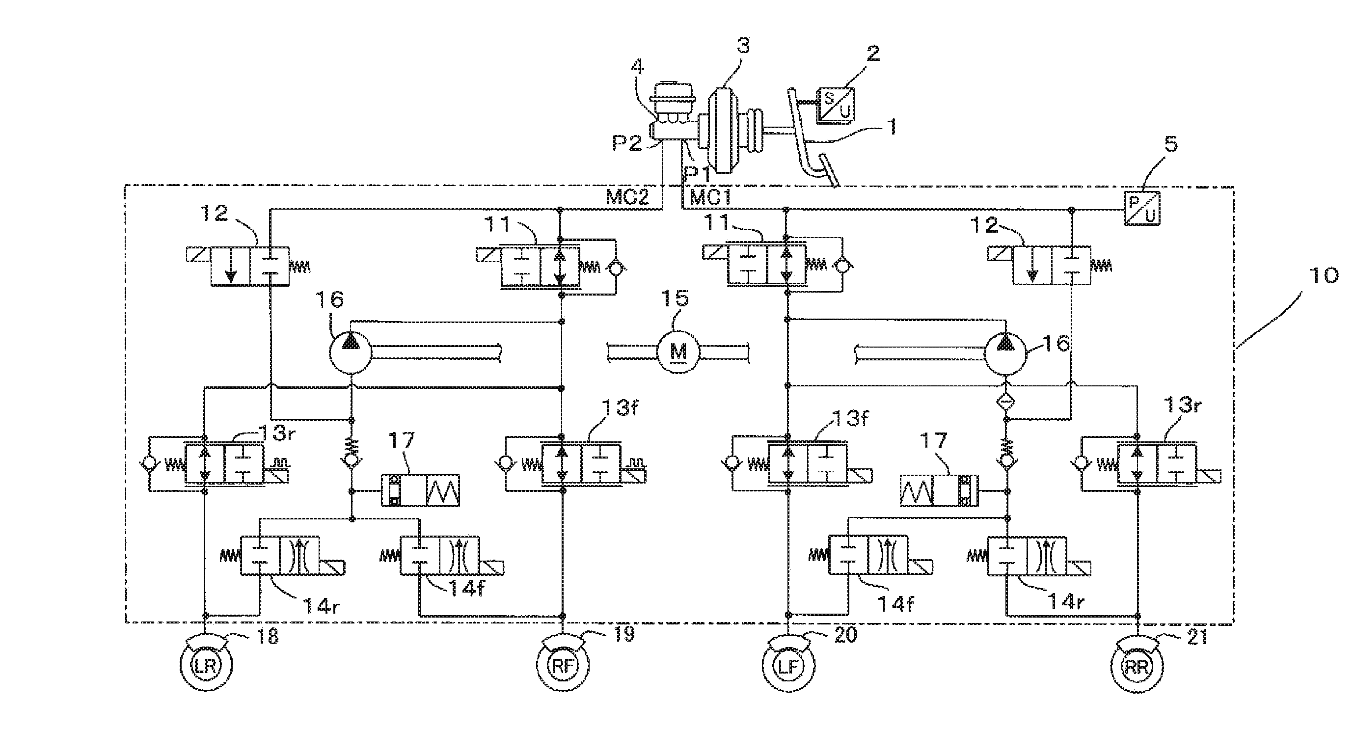
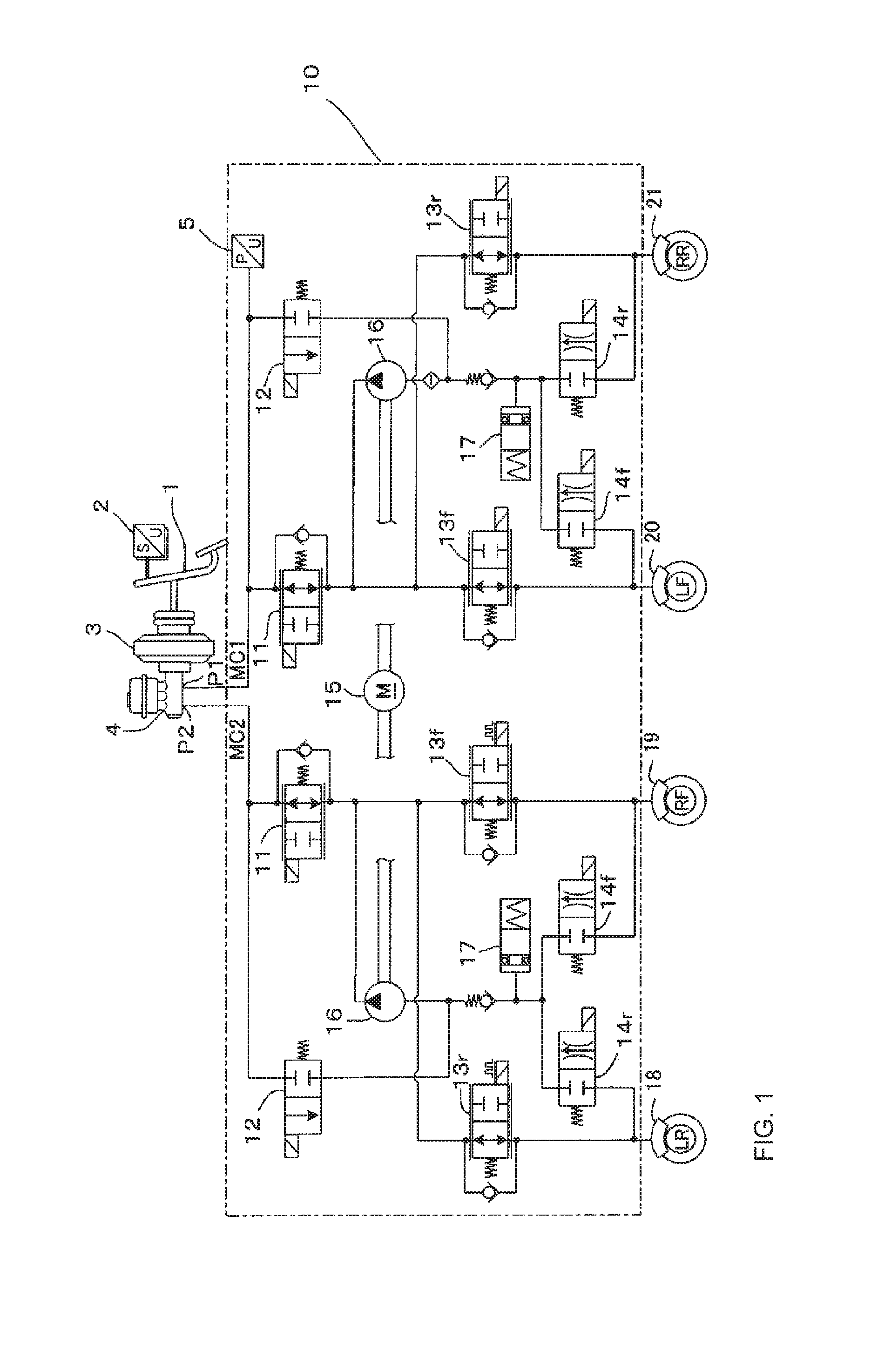
[0030]FIG. 1 illustrates an example of a hydraulic circuit 10 configuring a hydraulic brake in a brake device for a vehicle to which the present invention is applied. As illustrated in FIG. 1, the present embodiment includes two brake lines, and is applied to a hydraulic circuit of a so-called X-type piping method in which brakes act on a set of two wheels which are one front wheel and one rear wheel diagonal to the one front wheel in each system. However, the hydraulic circuit to which the present invention is applied is not limited to the X-type piping method, for example, and may brake separately a front wheel side and a rear wheel side, which is a so-called ∥-type piping method. In addition, the present invention is not limited to only a four-wheel vehicle, and can be widely applied to a vehicle which includes a two-wheel vehicle.

[0031]The present invent...


PUM


Abstract

A brake device for a vehicle, that includes at least a first hydraulic brake and a second hydraulic brake which produce hydraulic brake forces, and a regenerative brake which produces a regenerative brake force, and that performs a distribution of the hydraulic brake force and the regenerative brake force with respect to a driver request brake force.

Description

BACKGROUND OF THE INVENTION[0001]The present invention relates to a brake device for a vehicle and a control method thereof, and particularly to a brake device which includes a hydraulic brake and a regenerative brake for producing a regenerative brake force, and which can distribute a braking force between a hydraulic brake force and the regenerative brake force, and a control method thereof.[0002]As a brake device for a vehicle of the related art, a brake device for a vehicle, which includes both a hydraulic brake for producing a hydraulic brake force using a hydraulic pressure being produced according to a brake operation of a driver, and a regenerative brake for producing a regenerative brake force, and which performs a regenerative cooperation by distributing a braking force between the hydraulic brake force and the regenerative brake force, is known.[0003]An object of the regenerative brake being used for such a brake device for a vehicle is to convert kinetic energy of a vehi...

Claims


Application Information

Patent Timeline
Patent Type & Authority Patents(United States)
IPC IPC(8): B60L7/18B60T8/48B60T13/58B60T13/68B60T15/02B60T1/10
CPCB60L7/18B60T1/10B60T8/4872B60T13/585B60T13/686B60T15/028B60T2270/604
Inventor NAGAKURA, YASUTAKAHAKIAI, MOTOMU
Owner BOSCH CORP
Learn More