
LED lighting apparatus emitting controlled spatial illumination light

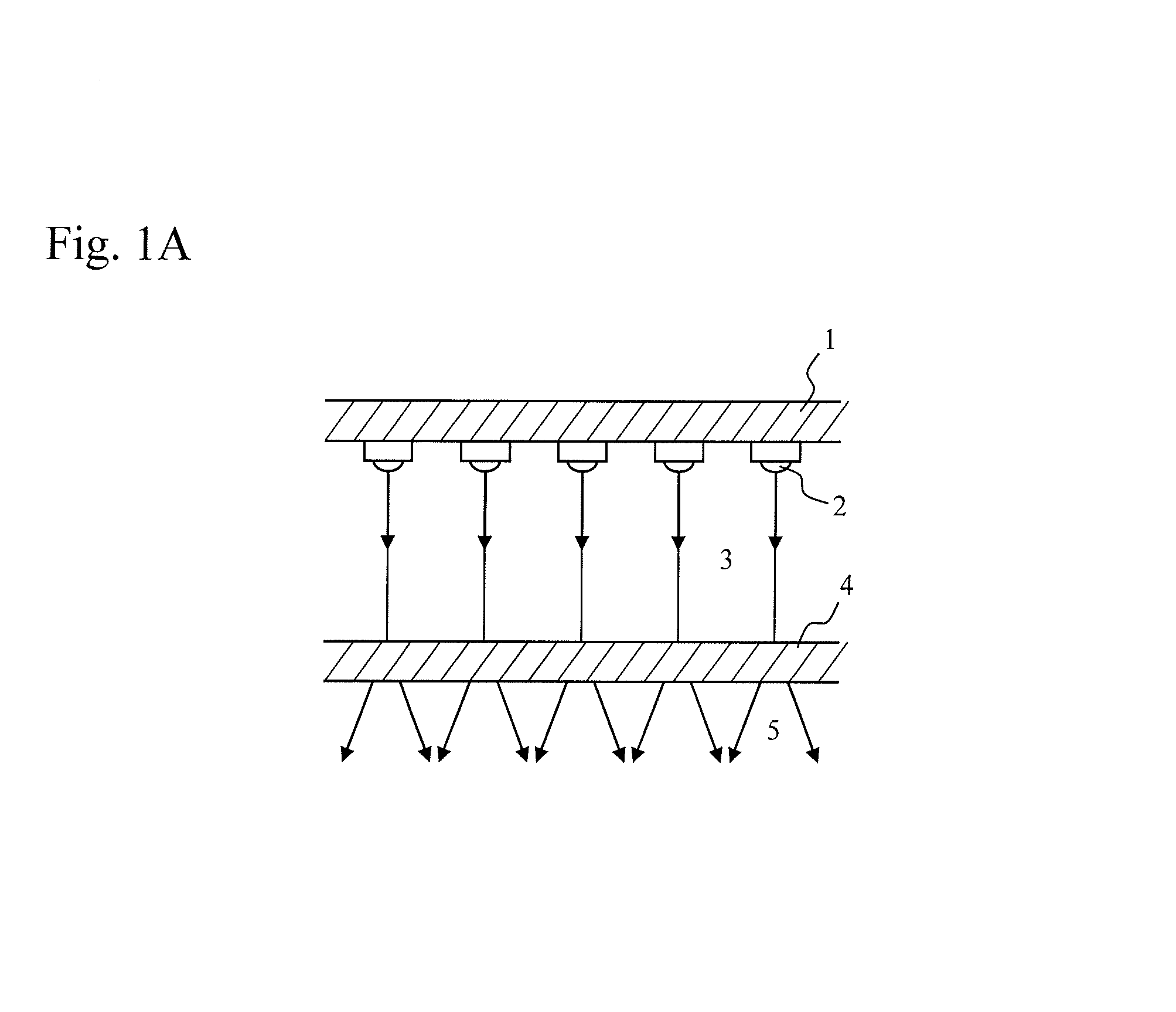
a technology of led lighting and spatial illumination, which is applied in the field of led lighting apparatus, can solve the problems of not being able to illuminate large areas of a room, and not being able to change the brightness partially, so as to achieve the effect of improving lighting quality and a lot of energy saving and environmental problems

Active Publication Date: 2016-05-03
KATAOKA SHOEI +1
View PDF26 Cites 3 Cited by
  • Summary
  • Abstract
  • Description
  • Claims
  • Application Information

AI Technical Summary

Benefits of technology

The LED lighting apparatus described in this patent allows for precise control over the distribution of illumination light. This means that creating new and innovative lighting effects is possible, such as concentrating, dispersing, or scattering light for specific areas, or illuminating an entire room with indirect lighting. The invention also results in significantly improved lighting quality. Additionally, it replaces two separate lighting apparatuses with one, contributing to energy-saving and environmental concerns.

Problems solved by technology

However, it was not able to illuminate large areas of a room.
It was not possible for LEDs to change the brightness partially as required.

Method used


Image

  • LED lighting apparatus emitting controlled spatial illumination light
  • LED lighting apparatus emitting controlled spatial illumination light
  • LED lighting apparatus emitting controlled spatial illumination light

Examples


Embodiment Construction

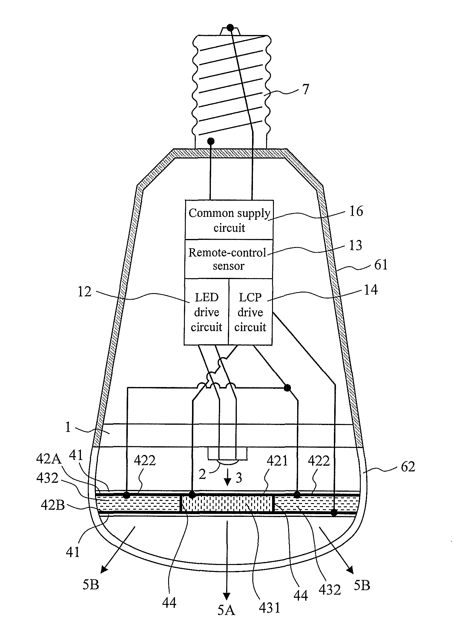
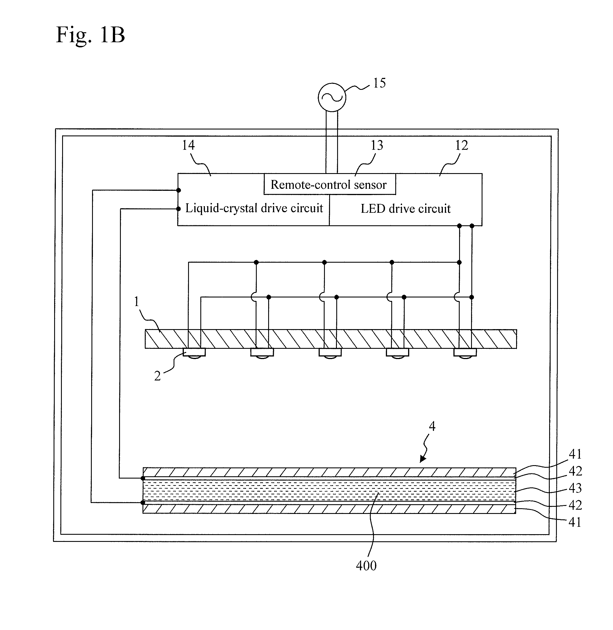
[0092]With reference to FIG. 1B, the structure of an LED lighting apparatus of the present invention is described in detail. The lighting apparatus in accordance with an embodiment of the present invention includes: LEDs (light-emitting diodes) 2 which is mounted on a substrate 1, a liquid crystal panel 4, an LED drive circuit 12, a remote control sensor (remote-control signal receiver) 13, and a liquid-crystal drive circuit 14. The LED drive circuit 12, the remote-control sensor 13, and the liquid-crystal drive circuit 14 are connected to a commercial power supply 15 for domestic use. That is, the LED drive circuit and the liquid-crystal drive circuit are provided with voltages from a common commercial power supply. Transparent electrodes 42 are connected to the liquid-crystal drive circuit 14. The LEDs (light-emitting diodes) 2 are connected to the LED drive circuit 12. Embedding a human detection sensor in the lighting apparatus in accordance with an embodiment of the present inv...


PUM


Abstract

Light from an LED (light-emitting diodes) has strong directional characteristics; therefore, lighting over large area, as well as control of the quality or the distribution of lighting was impossible. Placing a liquid-crystal panel in front of an LED (light-emitting diodes) enables to control light from the LED and the quality or the distribution of lighting.

Description

TECHNICAL FIELD[0001]The present invention relates to a lighting apparatus using LEDs that can control the quality and the area of lighting by combining LEDs with a liquid-crystal panel.BACKGROUND ART[0002]An LED, which emits light by applying a direct voltage to a p-n junction in a compound semiconductor, has been used for home lighting as a result of the recent remarkable progress of technologies. Multi-layered p-n junctions, as well as LEDs (light-emitting diode) mounted on a board have been made it possible to use for high power lighting. An LED lighting, however, because of the structure of its light emitting part, has strong directional characteristics; therefore the use of the LED lighting was limited to downlights. Unlike conventional incandescent bulbs or florescent lamps, an LED lighting was not able to illuminate large areas of a room. It was also not able to control the quality or the area of lighting.PRIOR ART DOCUMENTSPatent Documents[0003]Patent Document 1: JP-A-2008-...

Claims


Application Information

Patent Timeline
Patent Type & Authority Patents(United States)
IPC IPC(8): G02F1/13G02F1/1335F21V14/00F21K99/00H05B37/02G02F1/1334G02F1/1333F21S8/04F21V3/00F21V9/40F21W131/40F21Y111/00
CPCF21V14/003F21K9/135F21S8/04G02F1/1334G02F1/133371G02F1/133526G02F1/133603H05B37/0245F21V3/00F21W2131/40F21Y2101/02F21Y2111/005F21K9/232F21Y2115/10F21Y2107/30H05B47/175G01B11/00H05K13/04H05K13/08
Inventor KATAOKA, SHOEIKATAOKA, TERUYUKI
Owner KATAOKA SHOEI
Learn More