
Systems and techniques for compensation for the thermo-optic effect in active optical fibers

a technology of active optical fibers and compensating systems, applied in the field of fiber optical technology, can solve problems such as the degradation of the ambient temperature loss characteristics of fibers, and achieve the effect of preventing the degradation of the single-modedness of a large-mode-area fiber and preventing the degradation of the bandpass characteristics of an optical fiber filter

Active Publication Date: 2016-04-26
OFS FITEL LLC
View PDF4 Cites 51 Cited by
  • Summary
  • Abstract
  • Description
  • Claims
  • Application Information

AI Technical Summary

Benefits of technology

The invention describes the use of bend compensation to prevent degradation of the quality of a fiber's signal and filter's bandpass characteristics. Essentially, the invention helps to ensure that the fiber remains pure and the filter's performance is not impacted by bending or other external factors. This technology can improve the reliability and performance of optical fibers and filters in various applications such as communication systems and sensing devices.

Problems solved by technology

The thermal index gradient, in the absence of a compensating index gradient, would result in degradation of the fiber's ambient temperature loss characteristics.

Method used


Image

  • Systems and techniques for compensation for the thermo-optic effect in active optical fibers
  • Systems and techniques for compensation for the thermo-optic effect in active optical fibers
  • Systems and techniques for compensation for the thermo-optic effect in active optical fibers

Examples


Embodiment Construction

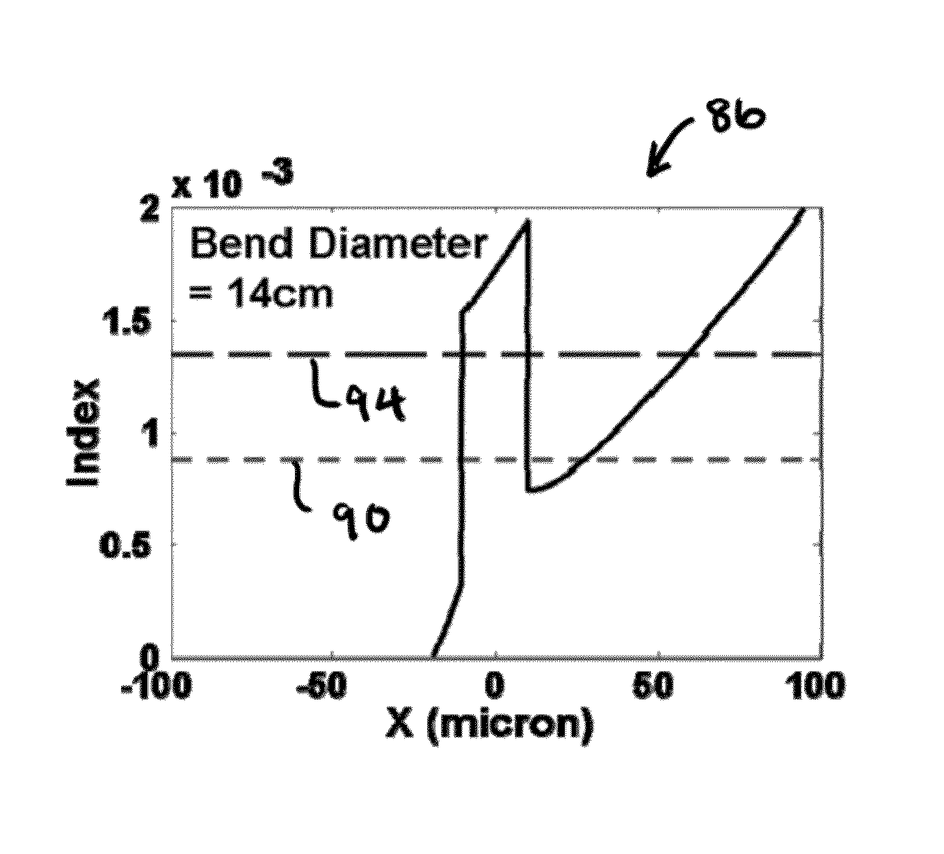
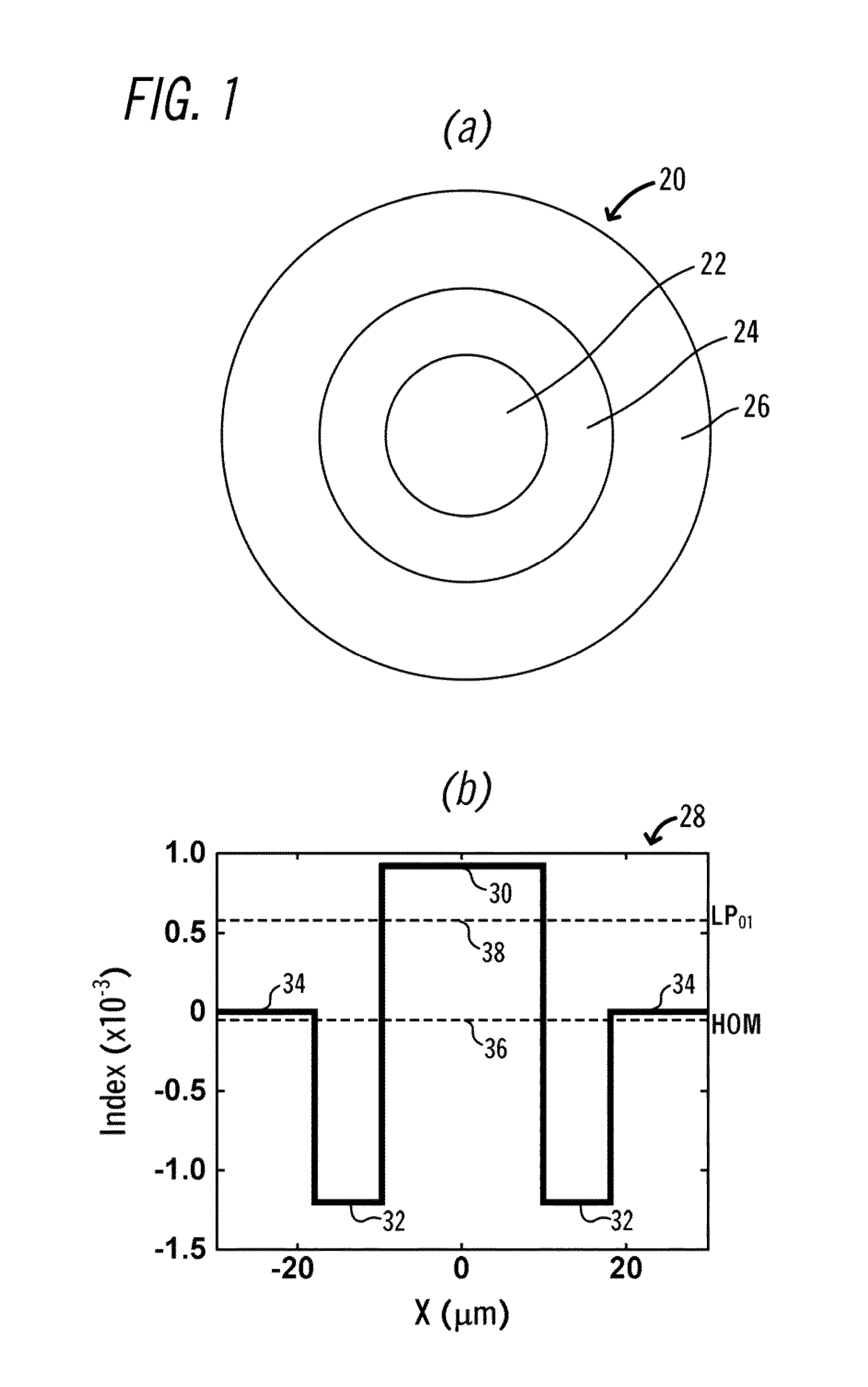
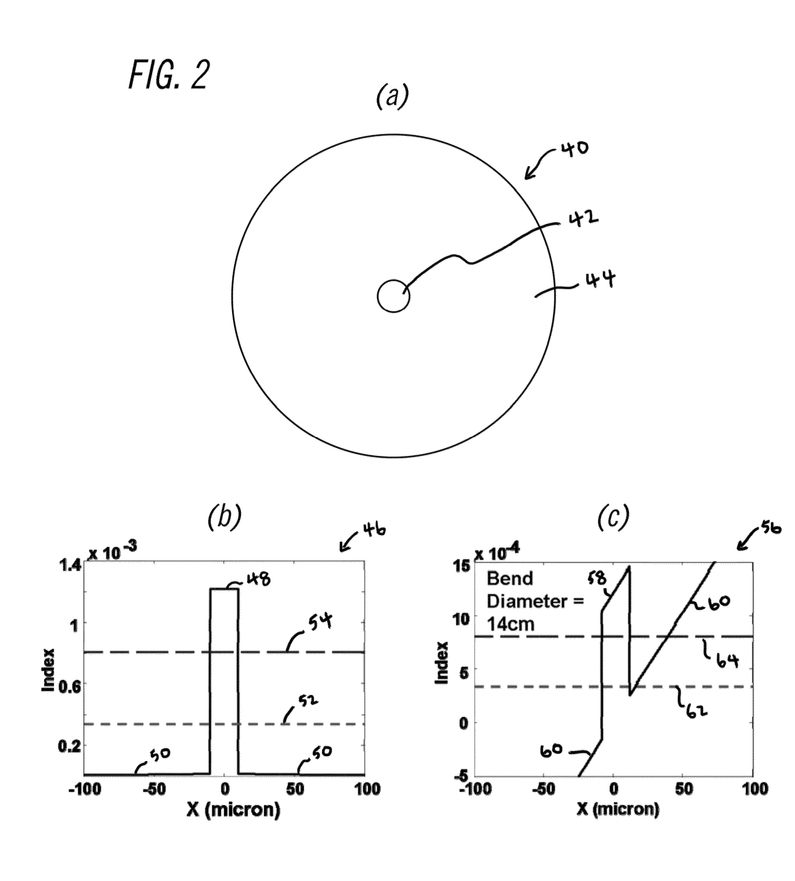
[0028]An aspect of the invention provides optical fiber layouts that compensate for the thermo-optic effect in optical fibers. According to a practice of the invention, thermo-optic compensation is provided for an optical fiber by arranging the fiber according to a scheme comprising specific length-varying curvatures. In one example, described below, the length-varying curvature is configured to provide first-order compensation for the index gradient created by the thermo-optic effect at each given fiber length. Equivalently, the length-varying curvature is configured to provide a reasonable level of compensation for the level of HOM loss or wavelength-selective loss at each given fiber length.

[0029]It is noted that fiber layouts according to the present invention can take a number of different shapes (e.g., circular, elliptical, figure eight, kidney-shaped, and the like) and forms, including for example: coils, spirals, helixes, serpentine forms, and variations and combinations the...


PUM


Abstract

A technique is described for providing compensation for the thermo-optic effect in a large-mode-area optical fiber, filter fiber, or the like. An optical fiber is provided having a refractive index profile with ambient temperature loss characteristics including a low loss for a first type of light and a high loss for a second type of light. A hot region of the fiber connected into an optical system is identified, in which a thermal index gradient is induced in the fiber. The thermal index gradient, in the absence of a compensating index gradient, would result in degradation of the fiber's ambient temperature loss characteristics. The fiber is arranged according to a layout having a position-varying bending diameter. Throughout the identified hot region, the fiber has a compensating bending diameter that induces a compensating index gradient in the fiber. Outside of the identified hot region, the fiber has an applied operating bending diameter that maintains the fiber's ambient temperature loss characteristics.

Description

BACKGROUND OF THE INVENTION[0001]1. Field of the Invention[0002]The present invention relates generally to the field of fiber optical technology, and in particular to systems and techniques for compensating for the thermo-optic effect in active optical fibers.[0003]2. Background Art[0004]Generally speaking, in a fiber laser operating at a high power level, it is desirable for the active gain fiber to be single-moded. Multimoded gain fibers pose a multitude of problems, including multimoded lasing, temporal instability, beam quality degradation, modal instability, and the like. Any of these issues can have catastrophic consequences in high-power fiber lasers and amplifiers.[0005]Fibers utilized for high-power applications typically cannot be reliably made truly single-moded using conventional designs, owing to the low index contrasts that are required, which can also result in enhanced sensitivity to bend loss. As a practical matter, this issue can be overcome by utilizing multimode ...

Claims


Application Information

Patent Timeline
IPC IPC(8): H01S3/067H01S3/102H01S3/13H01S3/10
CPCH01S3/102H01S3/06754H01S3/10007H01S3/1301H01S3/06704H01S3/06729H01S3/08045H01S3/08072
Inventor FINI, JOHN MRAMAKRISHNA, SUPRADEEPA V. S.
Owner OFS FITEL LLC
Learn More