Modulation method for improving signal conversion gain and high-gain modulator thereof

a modulator and signal conversion technology, applied in the field of signal modulation technology, can solve the problems of increasing the power consumption of the modulation circuit, and achieve the effects of reducing the power consumption of the entire circuit, avoiding energy waste, and improving the gain of the output signal

Active Publication Date: 2016-04-19
NAT TAIWAN UNIV
View PDF3 Cites 0 Cited by
  • Summary
  • Abstract
  • Description
  • Claims
  • Application Information

AI Technical Summary

Benefits of technology

[0012]In summary, in the modulation method for improving signal conversion gain and the high-gain modulator thereof according to the present invention, two modulation units are used for modulation by using local oscillation signals, each with different phase, to perform a fully duty cycle modulation of a group of input signals, so that signal energy is fully utilized and an energy waste is avoided, thereby improving the gain of the output signal and reduce the power consumption of the entire circuit (for example, a radio frequency transmitter circuit or a radio frequency receiver circuit).

Problems solved by technology

In a high-speed data transmission environment, with the increase of the signal transmission rate, the power consumption of the modulation circuit also increases.

Method used


Image

  • Modulation method for improving signal conversion gain and high-gain modulator thereof
  • Modulation method for improving signal conversion gain and high-gain modulator thereof
  • Modulation method for improving signal conversion gain and high-gain modulator thereof

Examples


Embodiment Construction

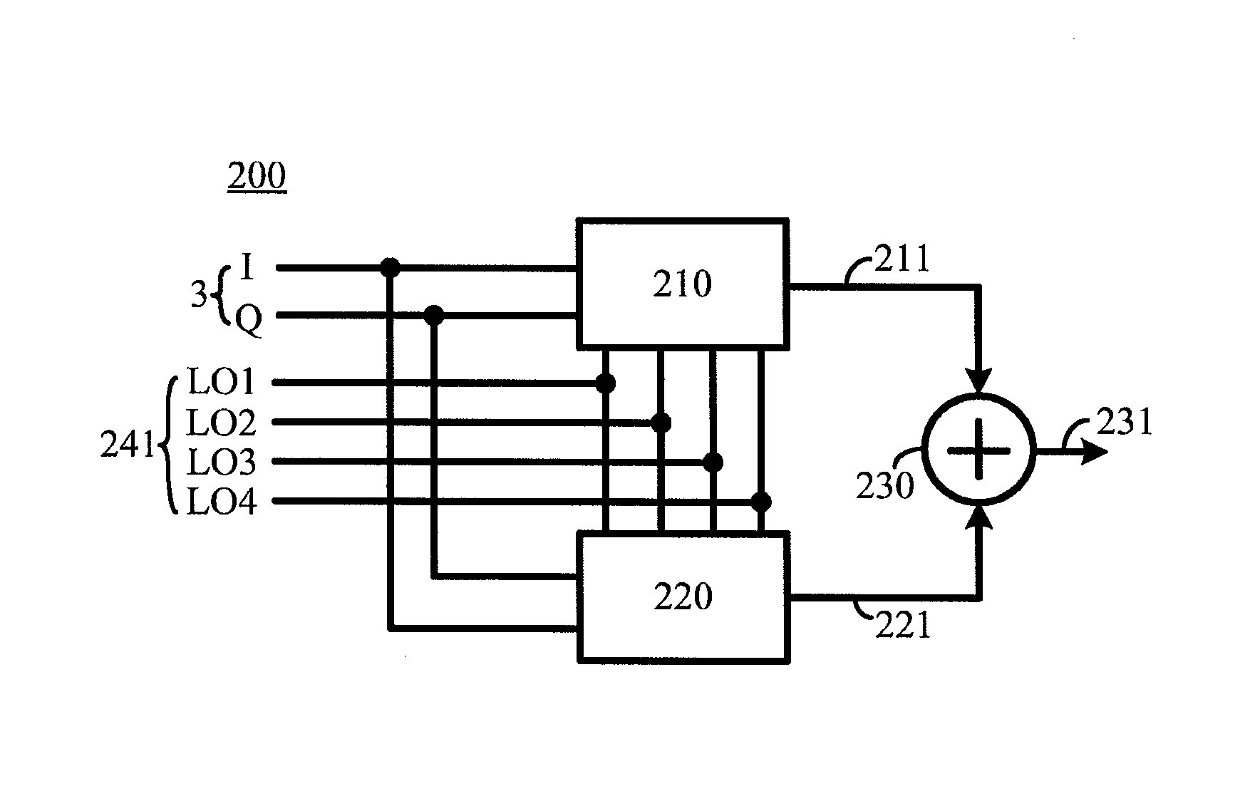
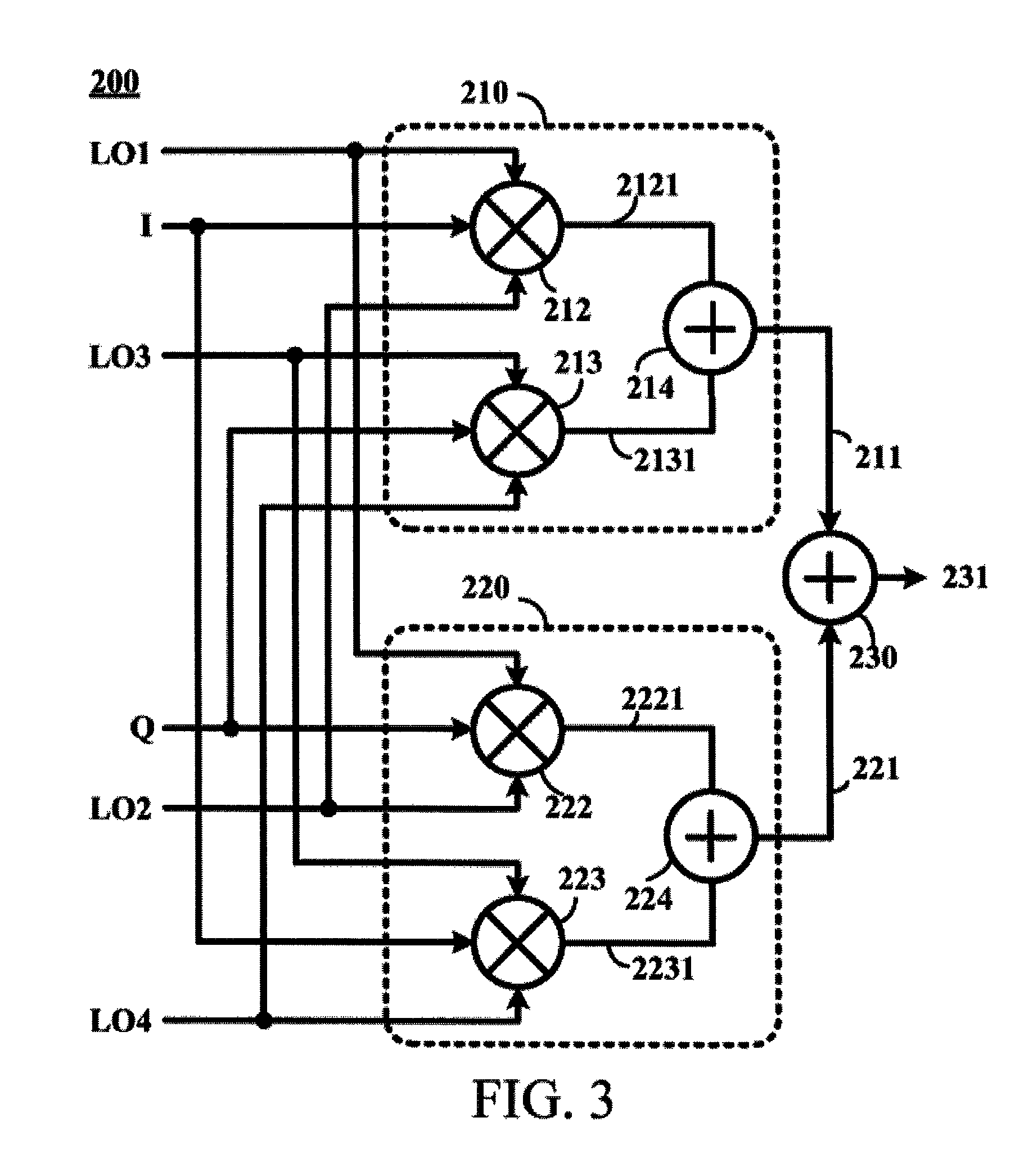
[0030]FIG. 2 is a general block diagram of a high-gain modulator according to an embodiment of the present invention. Referring to FIG. 2, a high-gain modulator 200 includes at least two modulation units (which are called a first modulation unit 210 and a second modulation unit 220 below) and an adder circuit 230.

[0031]Two input ends of the first modulation unit 210 are electrically connected to the previous stage circuit (not shown in the figure), and receive an input signal 3 from the previous stage circuit. Four control ends of the first modulation unit 210 are electrically connected to a signal source circuit (not shown in the figure), and receive a primary local oscillation signal 241 from the signal source circuit.

[0032]In the same way, two input ends of the second modulation unit 220 are electrically connected to the previous stage circuit (not shown in the figure), and receive the input signal 3 from the previous stage circuit. Four control ends of the second modulation unit...


PUM


Abstract

A modulation method includes sampling the first input signal by using the first local oscillation signal and the second local oscillation signal to generate the first sampled signal, sampling the second input signal by using the third local oscillation signal and the fourth local oscillation signal to generate the second sampled signal, sampling the second input signal by using the first local oscillation signal and the second local oscillation signal to generate the third sampled signal, sampling the first input signal by using the third local oscillation signal and the fourth local oscillation signal to generate the fourth sampled signal, adding the first sampled signal and the second sampled signal to produce the first modulation signal, adding the third sampled signal and the fourth sampled signal to generate the second modulation signal, and adding the first modulation signal and the second modulation signal to generate an output signal.

Description

CROSS-REFERENCES TO RELATED APPLICATIONS[0001]This non-provisional application claims priority under 35 U.S.C. §119(a) on patent application Ser. No. 103115672 and 103131747, filed in Taiwan, R.O.C. on Apr. 30, 2014 and Sep. 15, 2014, the entire contents of which are hereby incorporated by reference.BACKGROUND[0002]1. Technical Field[0003]The present invention relates to a signal modulation technology applied to a communication system, and in particular, to a modulation method for improving signal conversion gain and a high-gain modulator thereof.[0004]2. Related Art[0005]With the need for high speed and mobility communication, various wireless communications have been developed. In addition to conventional call function, a wireless communication apparatus also needs to support services such as high-definition video function, application software, and Wi-Fi. A modulation circuit is one of the important circuits in a wireless communication apparatus.[0006]FIG. 1 is a general block di...

Claims


Application Information

Patent Timeline
Patent Type & Authority Patents(United States)
IPC IPC(8): H04L27/00H04B1/04H03C3/00
CPCH04B1/04H03C3/00H03D7/1441H03D7/1458H03D7/1466
Inventor CHEN, YI-JANTSAI, LI-FAN
Owner NAT TAIWAN UNIV
Why Eureka
Try Eureka