
Control with hysteresis of an electronic device using a pulse-width modulated signal

a technology of pulse width and control, applied in the direction of power conversion systems, dc-dc conversion, instruments, etc., can solve the problems of high value of components, difficult compromises between requirements, and difficulty in limiting the frequency of operation, so as to achieve the effect of improving the situation

Active Publication Date: 2016-04-19
VITESCO TECH GERMANY GMBH
View PDF16 Cites 2 Cited by
  • Summary
  • Abstract
  • Description
  • Claims
  • Application Information

AI Technical Summary

Benefits of technology

The patent describes a new architecture for switch-mode devices that allows them to operate over a wide range of frequencies without passing through regions of forbidden frequencies. This is achieved by controlling the hysteresis comparators using a digital technology, which provides flexibility and ease of use. The main technical effect of this innovation is to improve the frequency response of switch-mode devices and avoid undulation variations in output voltage.

Problems solved by technology

This result is however obtained at the expense of difficult compromises between the requirements relating to the desired ranges of operation (current, voltage), and to the economically acceptable values of the most critical components of the switched-mode power supply, more particularly of the inductor and of the capacitor.
This is because limiting the frequency of operation requires the use of components having high values, hence costly and furthermore bulky, in order to obtain certain operating points at high currents and / or voltages.

Method used


Image

  • Control with hysteresis of an electronic device using a pulse-width modulated signal
  • Control with hysteresis of an electronic device using a pulse-width modulated signal
  • Control with hysteresis of an electronic device using a pulse-width modulated signal

Examples


Embodiment Construction

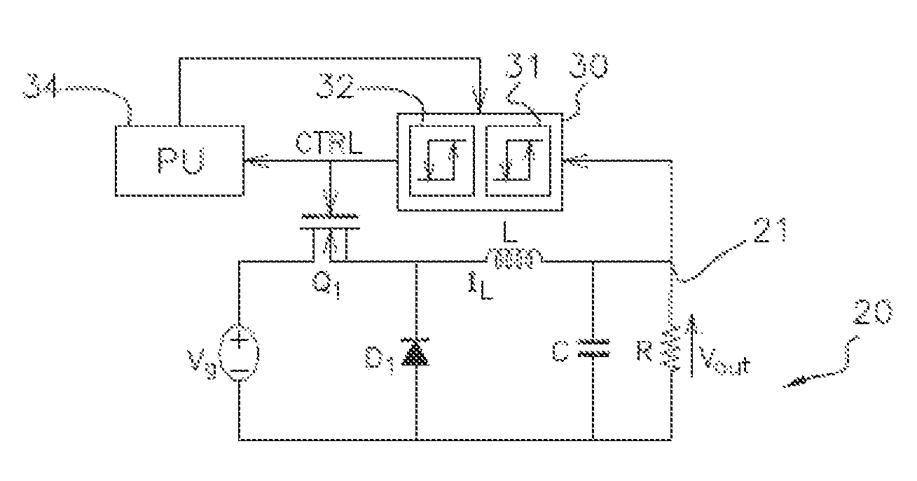
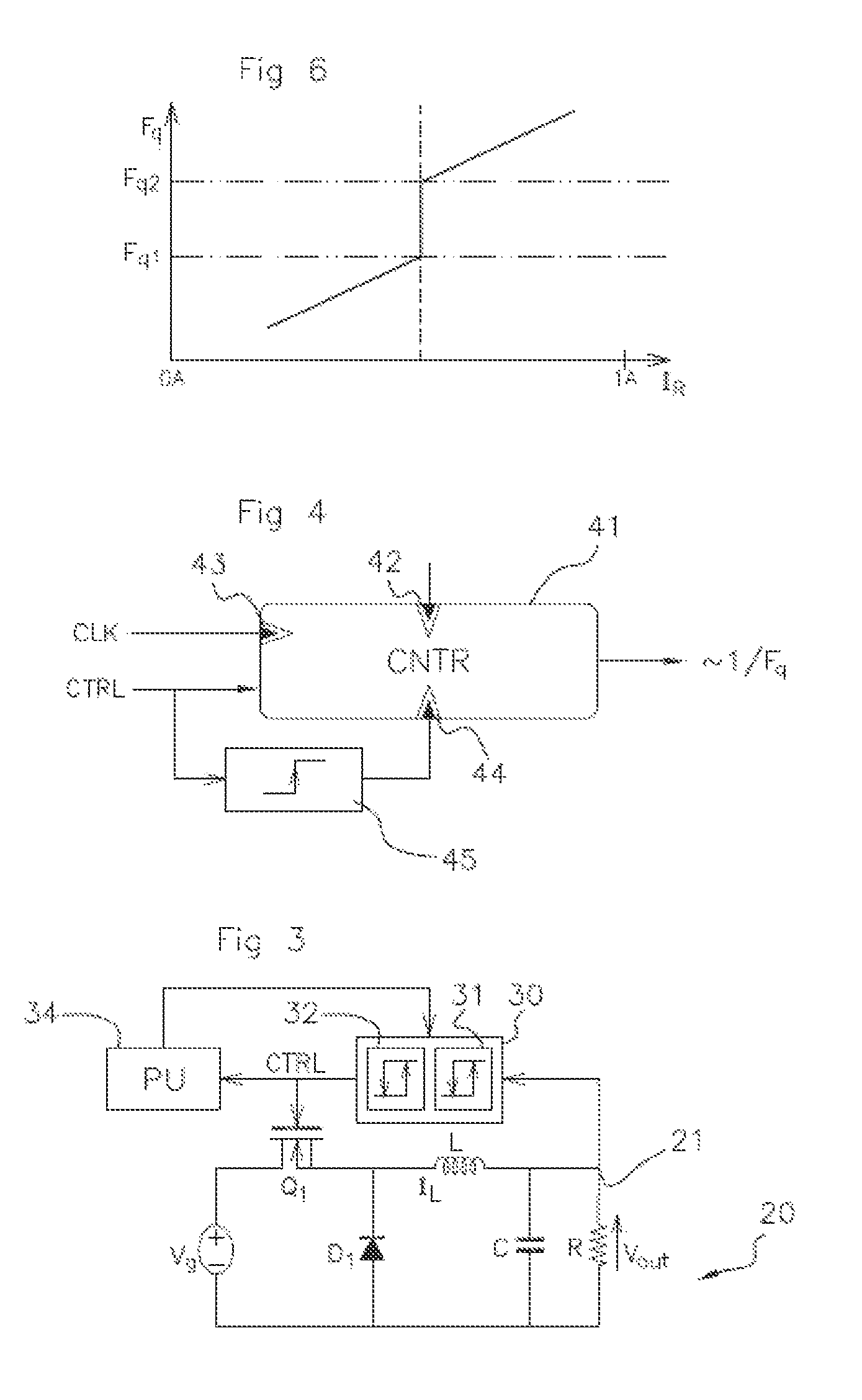
[0038]FIG. 1 shows one example of a device switched by a pulse-width modulated control signal. It has the structure of a DC-DC converter of the step-down voltage type (“Buck” converter structure).

[0039]In this structure, a chopping element, in general a power transistor Q1 such as a MOSFET (“Metal Oxide Semiconductor Field Effect Transistor”) or an IGBT (“Insulated Gate Bipolar Transistor”), switches from an ON state to an OFF state, or vice versa, depending on the changes in logic state of the control signal CTRL applied to its control gate.

[0040]In the case where Q1 is an NMOS transistor, its drain is for example coupled to the positive terminal of a source of DC voltage Vg whose negative terminal can be connected to ground. The source of Q1 is coupled to a first terminal of a load, symbolized here by a resistance R through an inductance L. The second terminal of the load R is coupled to ground. A capacitor C is coupled in parallel with the load R. Finally, a free-wheel diode D1 i...


PUM


Abstract

A device and switching method for a circuit for generating an output voltage (Vout) via a control signal (CTRL) with two pulse-width modulated states are described. The control signal (CTRL) frequency (Fq) is measured. In order to generate the control signal (CTRL), either a first hysteresis comparator (31) or a second hysteresis comparator (32) is enabled depending on the control signal (CTRL) measured frequency (Fq). Advantageously, the voltage thresholds of the hysteresis comparators and at least one frequency threshold can be chosen in such a manner as to avoid the control signal (CTRL) frequency (Fq) entering into forbidden frequency bands.

Description

BACKGROUND OF THE INVENTION[0001]1. Field of the Invention[0002]The present invention generally relates to switched electronic devices with hysteresis control, and more particularly, to switched-mode power supplies (or SMPS) of this type.[0003]The invention is applicable, in particular, to switched-mode power supplies for supplying power to automobile vehicle electronic control units.[0004]2. Description of the Related Art[0005]Hysteresis switched-mode power supplies are switched electronic devices, typically controlled by a Pulse Width Modulation (or PWM) signal with two states, whose changes of state result from the comparison of a controlled value with a low threshold and with a high threshold.[0006]This signal has a control frequency which varies as a function of the operating point (voltage, current). With a substantially constant output voltage, it varies in a continuous manner with the value of the output current. The higher the output current absorbed by the load, the higher...

Claims


Application Information

Patent Timeline
IPC IPC(8): G05F1/46H02M3/156
CPCH02M3/156H02M3/1563
Inventor LE-HUNG, FREDERICSAINT-MACARY, STEPHANE
Owner VITESCO TECH GERMANY GMBH
Learn More