
Distributed power delivery to a processing unit

a technology of distributed power and processing unit, which is applied in the direction of power supply for data processing, instruments, measurement devices, etc., can solve the problems of waste and/or dissipation of electric power by different processing units, consumption and dissipation of heat amounts to electric power wasted and/or dissipated by printed circuit boards, etc., to reduce power consumption, improve power delivery efficiency, and reduce power dissipation

Active Publication Date: 2016-04-19
NVIDIA CORP
View PDF16 Cites 1 Cited by
  • Summary
  • Abstract
  • Description
  • Claims
  • Application Information

AI Technical Summary

Benefits of technology

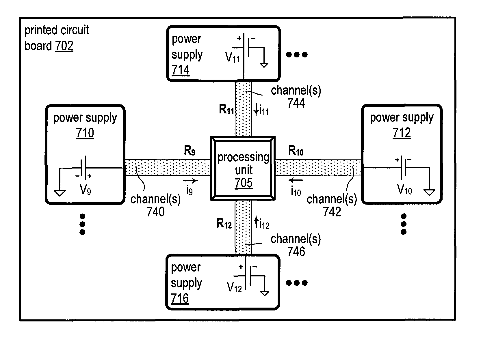
The disclosed approach improves the efficiency of power delivery to a processing unit by distributing power phases around it. This helps to reduce power dissipation in printed circuit boards, which allows batteries to supply power for longer periods of time.

Problems solved by technology

A processing unit and other circuitry on a printed circuit board consume and dissipate electric power.
Such operations of a processing unit are naturally associated with a non-zero amount of wasted and / or dissipated electric power.
Thus, the dissipated heat amounts to wasted and / or dissipated electric power of the printed circuit board.
Different processing units consume and dissipate varying degrees of electric power.
For example, a processing unit in a mobile phone may consume and dissipate just a few hundred milliwatts of electricity.
A microcontroller of an embedded system may consume and dissipate a few milliwatts.
In comparison, a processing unit in a general purpose personal computer, such as a desktop or a laptop, may consume and dissipate significantly more power because of the higher complexity and speed of a personal computer.
Such a microelectronic processing unit may consume and dissipate power in the order of a few watts to hundreds of watts.
Historically, early processing units implemented with vacuum tubes consumed power on the order of many kilowatts.
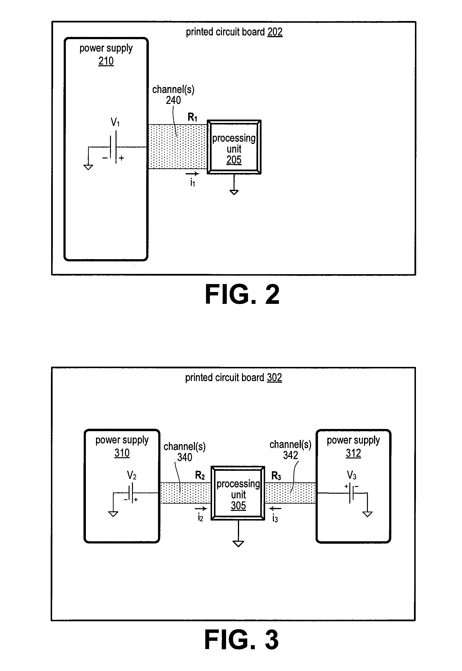
In addition, physical designs of printed circuit boards oftentimes include a processing unit coupled to a single power supply on one side of the processing unit, even in cases where the single power supply delivers multiple phases of power.
Unfortunately, in such designs (e.g., single power supply on one side of a processing unit), electric power is oftentimes unnecessarily dissipated.

Method used


Image

  • Distributed power delivery to a processing unit
  • Distributed power delivery to a processing unit
  • Distributed power delivery to a processing unit

Examples


Embodiment Construction

[0018]In the following description, numerous specific details are set forth to provide a more thorough understanding of the present invention. However, it will be apparent to one of skill in the art that the present invention may be practiced without one or more of these specific details. In other instances, well-known features have not been described in order to avoid obscuring the present invention.

System Overview

[0019]FIG. 1 is a block diagram illustrating a computer system 100 configured to implement one or more aspects of the present invention. Computer system 100 includes a central processing unit (CPU) 102 and a system memory 104 that includes a device driver 103. CPU 102 and system memory 104 communicate via an interconnection path that may include a memory bridge 105. Memory bridge 105, which may be, e.g., a Northbridge chip, is connected via a bus or other communication path 106 (e.g., a HyperTransport link) to an input / output (I / O) bridge 107. I / O bridge 107, which may be...


PUM


Abstract

Technology is provided for distributed power delivery to a processing unit on a printed circuit board. In one example, a printed circuit board includes a processing unit coupled to multiple power channels, including first channels on a first side of the processing unit, and second channels on a second side of the processing unit. The printed circuit board further includes a first power supply coupled to the processing unit via the first channels, and a second power supply coupled to the processing unit via the second channels. The processing unit is configured to receive a total current, including currents drawn substantially simultaneously from the first power supply and the second power supply. The total current is about equivalent to a current the processing unit would draw from a single power supply.

Description

BACKGROUND OF THE INVENTION[0001]1. Field of the Invention[0002]The present invention generally relates to integrated circuits and, more specifically, to distributed power delivery to a processing unit on a printed circuit board.[0003]2. Description of the Related Art[0004]A processing unit and other circuitry on a printed circuit board consume and dissipate electric power. Examples of such a processing unit include, without limitation, a graphics processing unit (GPU) and a central processing unit (CPU). Other circuitry coupled to the processing unit includes, without limitation, electronic power channels that couple the processing unit to a power supply (e.g., battery) on the printed circuit board. A processing unit can consume electric power, for example, by switching devices (e.g., flip-flops, transistors, etc.) included within the processing unit. Such operations of a processing unit are naturally associated with a non-zero amount of wasted and / or dissipated electric power. For...

Claims


Application Information

Patent Timeline
Patent Type & Authority Patents(United States)
IPC IPC(8): G06F1/32G06F1/26
CPCG06F1/32G06F1/263
Inventor LOILER, BRIAN ROGER
Owner NVIDIA CORP
Learn More