
Vehicle control system

a technology of vehicle control and control system, which is applied in the direction of braking system, machine/engine, engine starter, etc., can solve the problems of vehicle unintentional movement, creep force, vehicle unintentional movement, etc., to prevent unintentional movement of the vehicle, improve the reliability of the vehicle, and prevent the effect of unintentional movemen

Active Publication Date: 2016-04-12
SUBARU CORP
View PDF13 Cites 4 Cited by
  • Summary
  • Abstract
  • Description
  • Claims
  • Application Information

AI Technical Summary

Benefits of technology

[0009]It is therefore an object of the present invention to provide a vehicle having a mechanical brake (e.g., an electric parking brake) with a vehicle control system which prevents unintentional movement of the vehicle due to an automatic stop of the drive power source, thereby providing improved reliability.
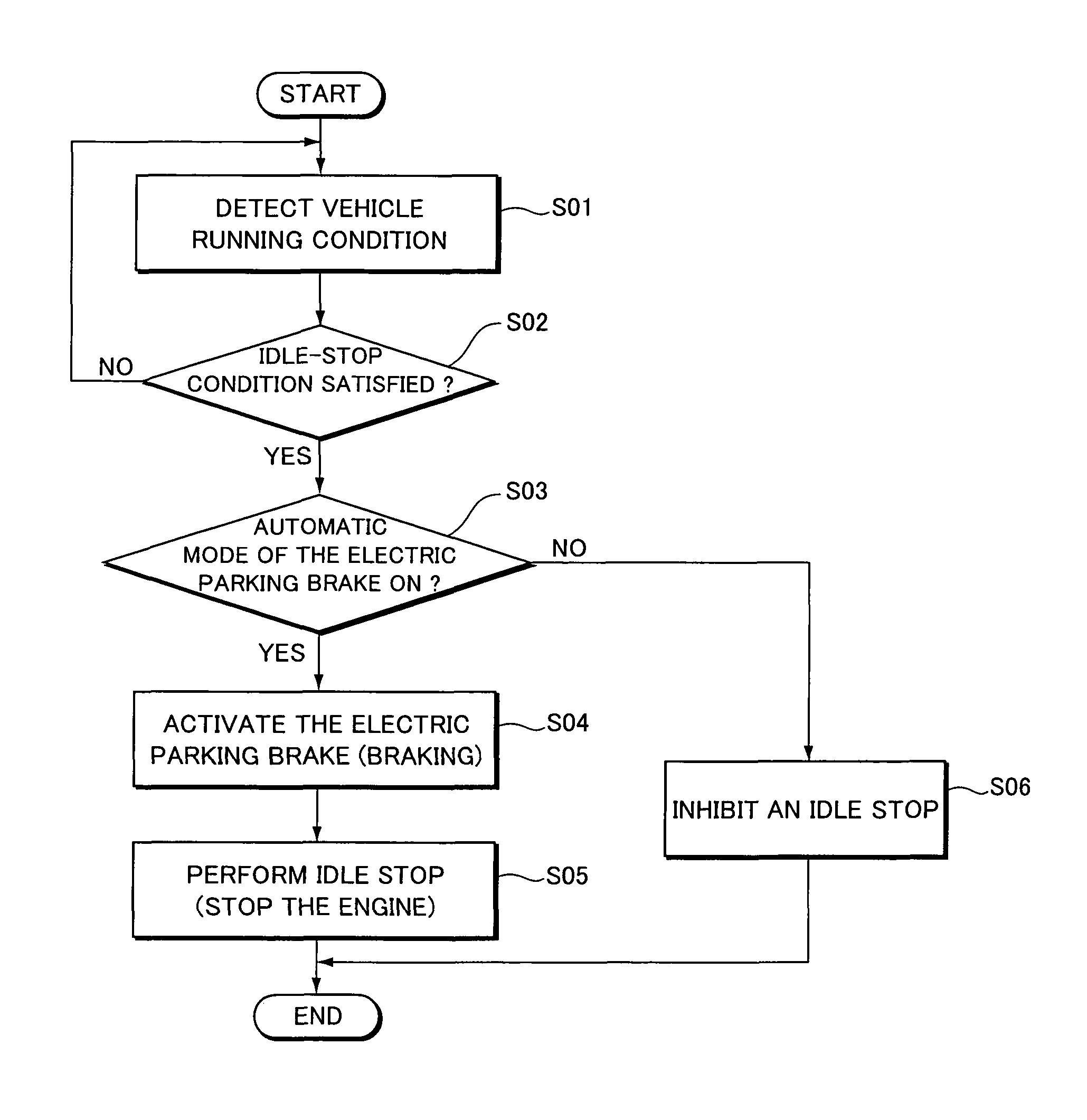
[0014]According to the present invention, an automatic stop of the drive power source is inhibited when the automatic mode of the brake control section is released. This makes it possible to prevent an automatic stop of the drive power source in a state in which the mechanical brake is released, and thus prevent unintentional movement of the vehicle.
[0015]On the other hand, an automatic stop of the drive power source can be inhibited when the automatic mode is released and a predetermined inclination is detected, thereby ensuring that unintentional movement of the vehicle caused by an inclination of the road surface is prevented.
[0016]Furthermore, according to the present invention, an automatic stop of the drive power source is inhibited when the diagnostic section for diagnosing the function of the brake control section outputs a fail signal, thereby preventing an automatic stop from being made in the presence of a failure or the like in the brake control section. This allows for preventing unintentional movement of the vehicle caused by loss in creep force on an inclining or declining road surface, thus providing improved reliability to the vehicle.

Problems solved by technology

However, when an idle stop is performed while the automatic mode is released in which the electric parking brake is automatically activated during a standstill of the vehicle, the vehicle may unintentionally start to move due to loss in creep force caused by the stop of the engine or due to reduction in braking force of the foot brake caused by the stop of the brake booster.
On the other hand, if an idle stop is performed not only when the automatic mode is released but also when the electric parking brake is out of order for some reason, the electric parking brake being not activated may likely cause the vehicle to start to unintentionally move.

Method used


Image

  • Vehicle control system
  • Vehicle control system
  • Vehicle control system

Examples


first embodiment

[0027]A description will now be made to a vehicle control system in accordance with a first embodiment of the present invention.

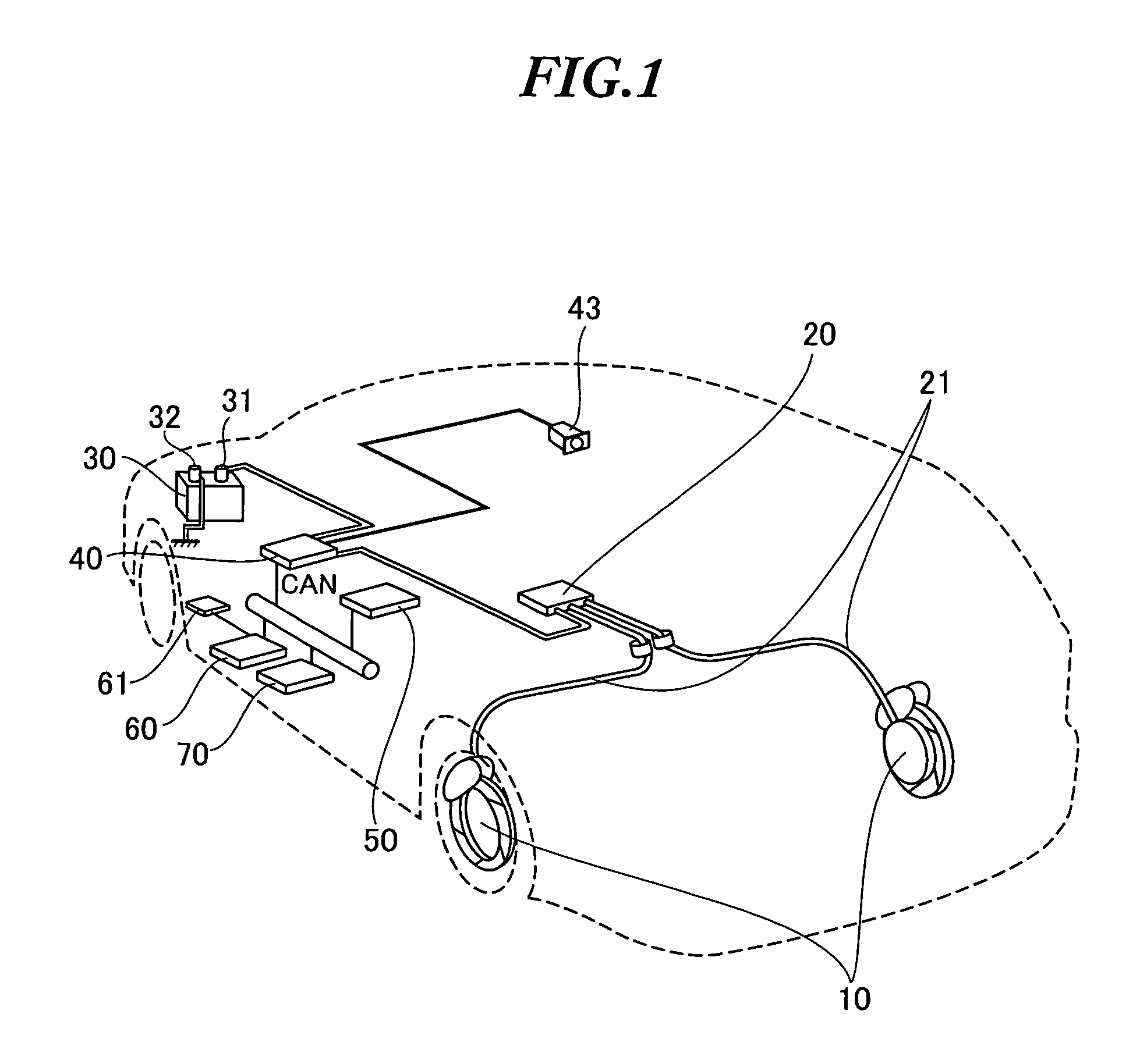
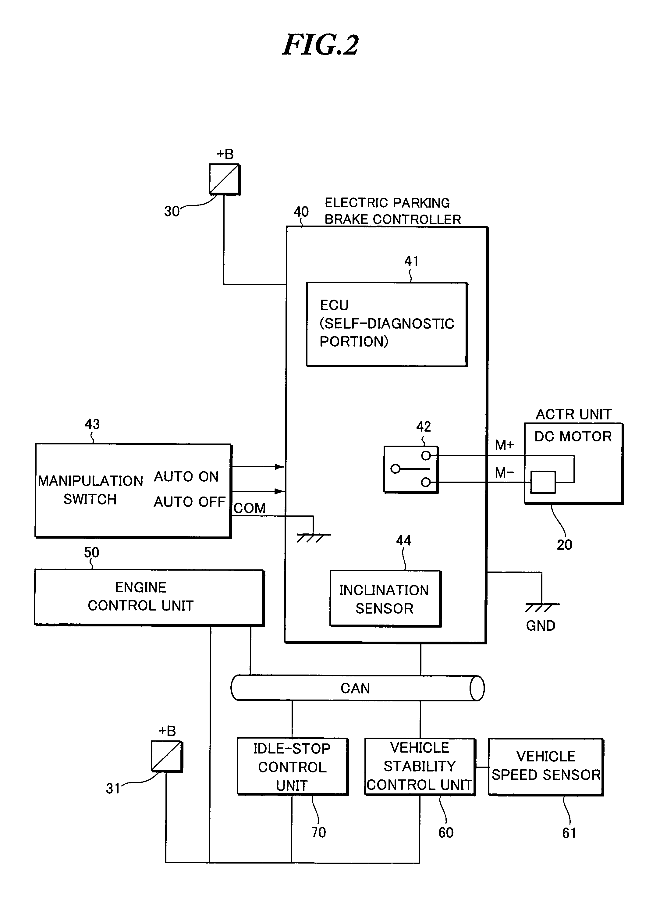
[0028]FIG. 1 is a schematic view illustrating the configuration of the vehicle control system of this embodiment. FIG. 2 is a block diagram illustrating the circuit configuration of the vehicle control system.

[0029]The vehicle control system includes a parking brake 10, an actuator unit 20, a battery 30, an electric parking brake controller 40, an engine control unit 50, a vehicle stability control unit 60, and an idle-stop control unit 70.

[0030]On the other hand, the vehicle employed in this embodiment is a passenger automobile which incorporates a gasoline engine as its drive power source.

[0031]The parking brake 10 is a braking mechanism for applying brakes to the drive wheels of the vehicle in order to prevent unintentional movement of the vehicle, e.g., when the vehicle is parked or at a stop. The brake 10 is installed at each of the right and left rear...

second embodiment

[0067]A second embodiment is adapted such that the idle-stop control unit 70 performs an idle stop only when the vehicle is detected to transition to a standstill state and the ECU 41 of the electric parking brake controller 40 does not output the fail signal (or the fail signal is OFF).

[0068]A description will now be made to the operation of the vehicle control system described above. FIG. 6 is a flowchart showing the operation of the vehicle control system related to the presence or absence of the fail signal of the electric parking brake. The steps of the operation will be described below in the order in which they appear.

101: Detecting the Running Condition>

[0069]The idle-stop control unit 70 detects the running condition of the vehicle. Here, for example, the running conditions of the vehicle include the speed of the vehicle (vehicle speed) calculated based on the vehicle speed pulse signal outputted by the vehicle speed sensor 61 and the presence or absence of the depression o...

modified examples

[0083]The present invention is not limited to the aforementioned embodiments, and various modifications and variations can be made thereto without departing from the scope of the present invention.[0084](1) The first and second embodiments inhibit an automatic stop of the drive power source when the automatic mode of the brake control section is released or when the diagnostic section outputs a fail signal. However, the condition for inhibiting the automatic stop of the drive power source is not limited to this condition but may be changed as appropriate. For example, an inclination sensor for detecting an inclination of the road surface may be used to inhibit the automatic stop of the drive power source only when the automatic mode is released and the inclination of the road surface is equal to or greater than a predetermined inclination. Alternatively, the automatic stop of the drive power source may be inhibited only when the diagnostic section outputs the fail signal and the inc...


PUM


Abstract

A brake control section can select an automatic mode in which a mechanical brake is automatically transitioned from a released state to a braking state in response to the running condition of a vehicle. A diagnostic section outputs a fail signal when an abnormal condition of the brake control section is detected. A power control section automatically stops a drive power source of the vehicle when the running condition of the vehicle satisfies a predetermined condition for determining a vehicle stop. When the automatic mode of the brake control section is released or when the diagnostic section outputs a fail signal of the brake control section, the power control section is inhibited to automatically stop the drive power source, so that an unintentional movement of the vehicle caused by an inclination of the road surface and the automatic stop of the drive power source can be prevented.

Description

[0001]The present application claims each priority from Japanese Patent Application Nos. 2006-017085 and 2006-022891, the respective disclosures of which are incorporated herein by reference.BACKGROUND OF THE INVENTION[0002]1. Field of the Invention[0003]The present invention relates to a vehicle control system which performs an automatic stop of a drive power source during a standstill of the vehicle and includes a mechanical brake driven by an actuator.[0004]2. Description of the Related Art[0005]Some vehicles such as automobiles are well known which are adapted to automatically stop (idle stop) the engine of the vehicle when the vehicle is stopped in order to improve fuel economy and reduce exhaust gas. One of the vehicles with such an idle-stop function is known to automatically activate an electric parking brake serving as a mechanical brake driven by an electric actuator during an idle stop in order to prevent unintentional movement of the vehicle due to an inclination of the ...

Claims


Application Information

Patent Timeline
Patent Type & Authority Patents(United States)
IPC IPC(8): B60T8/52B60T7/10B60T7/12B60T13/74B60W10/06B60W10/184B60W30/18F02N11/08B60W10/18
CPCB60T7/107B60T7/12B60T7/122B60T13/746B60W10/06B60W10/184B60W30/18018F02N11/0833B60W2710/065F02N2200/124Y02T10/48Y02T10/40
Inventor UCHIMURA, YUKIYAICHIKAWA, KATSUFUMINAKANO, TSUYOSHI
Owner SUBARU CORP
Learn More