Thermally assisted magnetic recording head with magnetic circuit parallel to substrate

a technology of magnetic recording head and magnetic circuit, which is applied in the direction of maintaining head carrier alignment, manufacturing head surface, instruments, etc., can solve the problems of reducing the thermal stability of magnetization in the magnetic grains, difficult to record information on an existing magnetic head, and difficult to obtain high magnetic gradient, etc., to achieve sufficient magnetic gradient, sufficient magnetic field intensity, and greater magnetic gradient

Active Publication Date: 2016-03-22
TDK CORPARATION
View PDF1 Cites 0 Cited by
  • Summary
  • Abstract
  • Description
  • Claims
  • Application Information

AI Technical Summary

Benefits of technology

[0015]The main magnetic pole end surface and the shield end surface are positioned on the same side in the down track direction (recording medium circumferential direction) with respect to the generator end surface, and, positioned close to each other in the cross track direction (recording medium radius direction). Consequently, the thermally assisted magnetic recording head of the present invention has a positional relationship where a conventional shield end surface is rotated around the main magnetic pole end surface by 90 degrees; i.e., a positional relationship where the main magnetic pole end surface and the shield end surface are arranged side-by-side in the cross track direction. Although the strong magnetic field intensity mainly appears along the cross track direction, a large magnetic gradient appears between the main pole end surface and the shield end surface along the down track direction, which is orthogonal to the cross track direction. Since the main magnetic end surface and the shield end surface are positioned close to each other in the cross track direction, sufficient magnetic field intensity can be obtained in the cross track direction; therefore, a sufficient magnetic gradient can be ensured in the down track direction. In addition, since the center line of the generator end surface extending in the down track direction extends between the opposing sides of the main magnetic pole end surface and the shield end surface, the NF light can be irradiated to the position where a great magnetic gradient in the down track direction can be obtained. Consequently, it is possible to obtain a greater magnetic gradient by the magnetic circuit in the vicinity where the NF light generator is positioned.

Problems solved by technology

On the other hand, decreasing the size of the magnetic grains, i.e., decreasing in the volumes of the magnetic grains, results in a decrease in the thermal stability of magnetization in the magnetic grains.
However, the greater anisotropic energy of the magnetic grains enhances the coercive force of the magnetic grains, making it difficult to record the information on an existing magnetic head.
In a conventional thermally assisted magnetic recording head having such a positional relationship between the NF light generator and the magnetic circuit, the below mentioned problem occurs.
Therefore, in the thermally assisted magnetic recording head where the NF light generator is positioned between both ends of the magnetic circuit, it is difficult to obtain a high magnetic gradient by the magnetic circuit in the vicinity where the NF light generator is positioned.

Method used


Image

  • Thermally assisted magnetic recording head with magnetic circuit parallel to substrate
  • Thermally assisted magnetic recording head with magnetic circuit parallel to substrate
  • Thermally assisted magnetic recording head with magnetic circuit parallel to substrate

Examples


Embodiment Construction

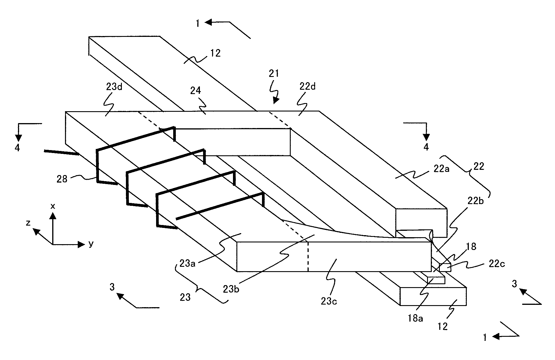
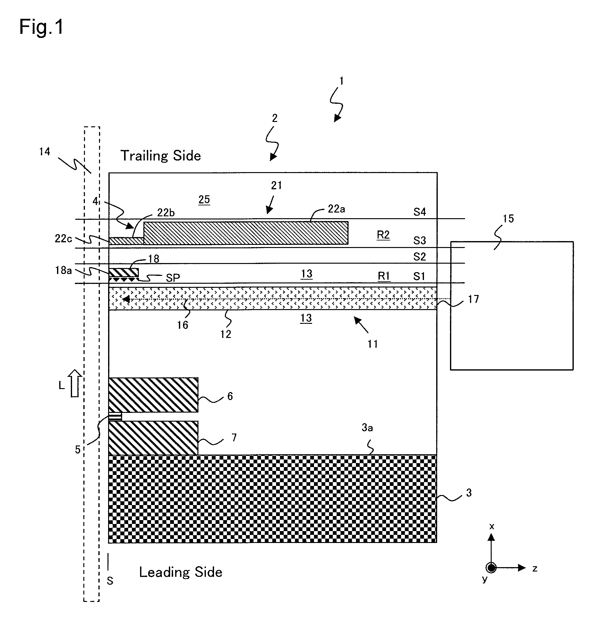
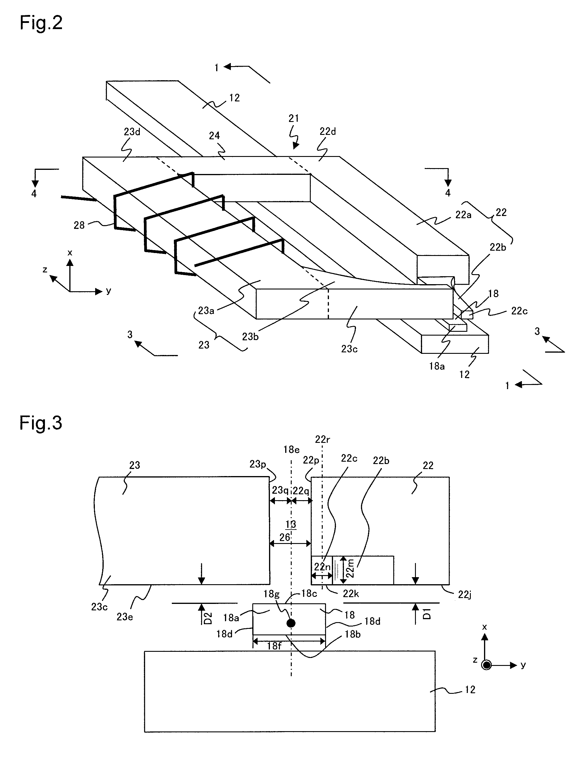
[0031]The thermally assisted magnetic recording head of the present invention is explained hereafter with reference to the drawings. FIG. 1 is a conceptual cross-sectional view of the thermally assisted magnetic recording head along line 1-1 of FIG. 2. FIG. 2 is a perspective view of a waveguide, a near-field light (NF light) generator and a magnetic recording element; FIG. 3 is a main part side view of the waveguide, the NF light generator and the magnetic recording element on the ABS along line 3-3 of FIG. 2; and FIG. 4 is a main part plan view of the waveguide, the NF light generator, the magnetic recording element and a magnetic recording medium 14 along line 4-4 of FIG. 2 viewed from the x direction.

[0032]In the specification, the x direction refers to the down track direction (recording medium circumferential direction) or a direction that is orthogonal to an integrated surface of a substrate where a magneto resistive (MR) element and a magnetic recording element are formed; t...


PUM

PropertyMeasurementUnit
thicknessaaaaaaaaaa
heightaaaaaaaaaa
degree of freedomaaaaaaaaaa

Abstract

A recording head has a near field light (NF light) generator generating NF light on a generator end surface that irradiates a magnetic recording (MR) medium; a main magnetic pole including a pole end surface facing an air bearing surface (ABS) that emits magnetic flux to the MR medium from the pole end surface; and a return shield having a shield end surface facing the ABS, that is magnetically linked with the main magnetic pole, and absorbs magnetic flux from the MR medium at the shield end surface. The pole end surface and the shield end surface are on the same side of the generator end surface in the down track direction, and are close to each other in the track crossing direction. A center line in the down track direction of the generator end surface extends between opposing sides of the pole end surface and the shield end surface.

Description

BACKGROUND OF THE INVENTION[0001]1. Field of the Invention[0002]The present invention relates to a thermally assisted magnetic recording head, and in particular relates to the configuration of a magnetic circuit used for recording.[0003]2. Description of the Related Art[0004]Recently, in a magnetic recording device typified by a magnetic disk apparatus, in association with high recording density, there is a demand for improvement in the performance of thin film magnetic heads and magnetic recording media. As the thin film magnetic head, composite type thin film magnetic heads are widely used in which a reproducing head having a magneto-resistive effect element (MR element) for reading, and a recording head having an induction-type electromagnetic transducer element for writing, are laminated on a substrate.[0005]The magnetic recording medium is a discontinuous medium where magnetic grains are aggregated, and each magnetic grain has a single magnetic domain structure. Each recording ...

Claims


Application Information

Patent Timeline
Patent Type & Authority Patents(United States)
IPC IPC(8): G11B5/00G11B5/31G11B5/187G11B5/60G11B5/11G11B5/127
CPCG11B5/6088G11B5/187G11B5/314G11B5/11G11B5/1278G11B2005/0021
Inventor AOKI, SUSUMUKOBAYASHI, TAKAFUMIHOSOI, RYOHIRATA, KEI
Owner TDK CORPARATION
Why Eureka
Try Eureka