Control valve

a control valve and valve body technology, applied in the direction of fluid pressure control, pressure relieving devices on sealing faces, instruments, etc., can solve the problems of water volume and obstruct the closing movement, and achieve the effect of reducing problems and/or drawbacks

Active Publication Date: 2016-03-15
FLOWCON INT
View PDF10 Cites 2 Cited by
  • Summary
  • Abstract
  • Description
  • Claims
  • Application Information

AI Technical Summary

Benefits of technology

[0006]It is an object of the invention to overcome or at least reduce the problems and / or drawbacks associated with the prior art control valves.
[0008]By providing a drain passage that allows the liquid in the pressure chamber to drain to the outlet of the control valve when the movable throttle member is in the position where it closes the exit openings the flow area regulator can be closed and the pressure regulating arrangement can move towards its closed position, without any counteractions of liquid trapped in the control valve.
[0025]By providing a drain passage that allows the liquid in the pressure chamber to drain to the outlet of the control valve the flow area regulator can be closed and the pressure regulating arrangement can move towards its closed position, without any counteractions of liquid trapped in the control valve.

Problems solved by technology

This has the drawback that an excessive amount of water can be trapped in the pressure chamber between the flow regulator and the differential pressure regulator and this trapped volume of water can in some circumstances obstruct the closing movement of one or the other or both regulators in turn.

Method used


Image

  • Control valve
  • Control valve
  • Control valve

Examples


Embodiment Construction

[0038]Example embodiments of the invention will now be described with reference to the drawing figures, in which like reference numerals refer to like parts throughout.

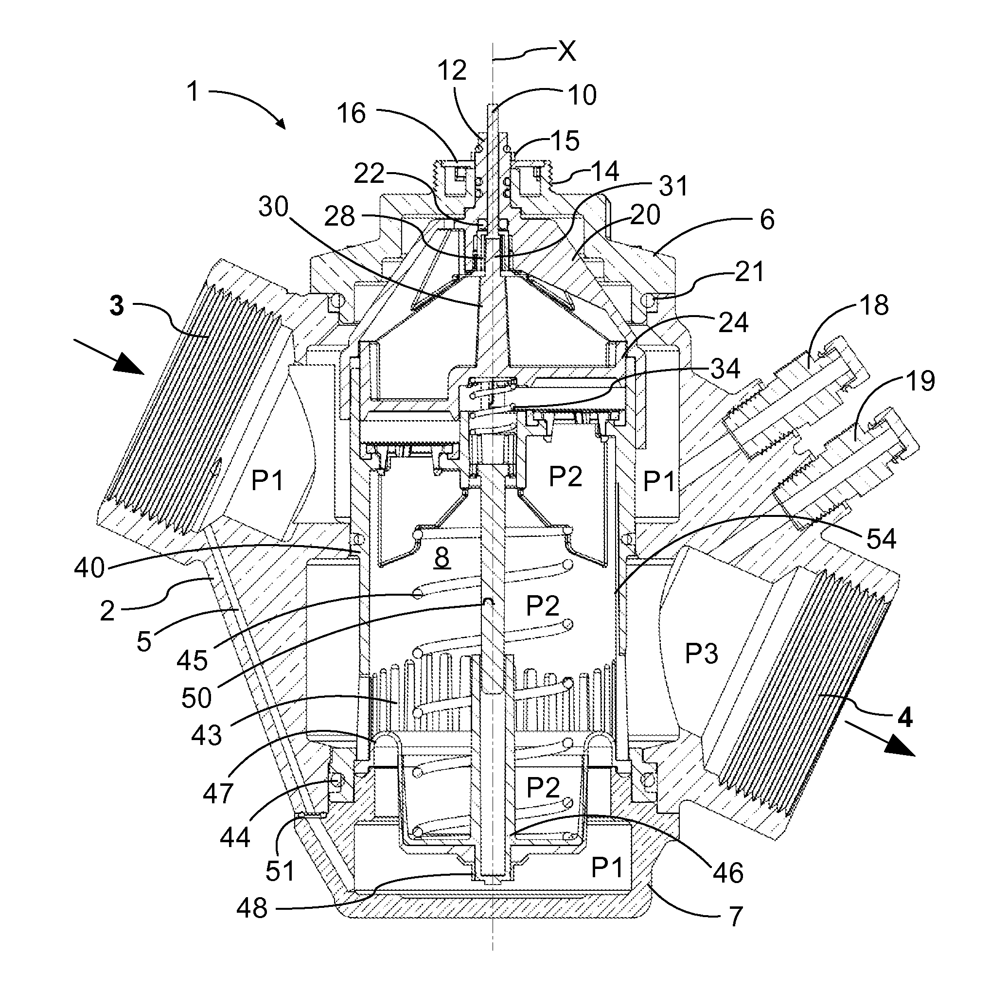
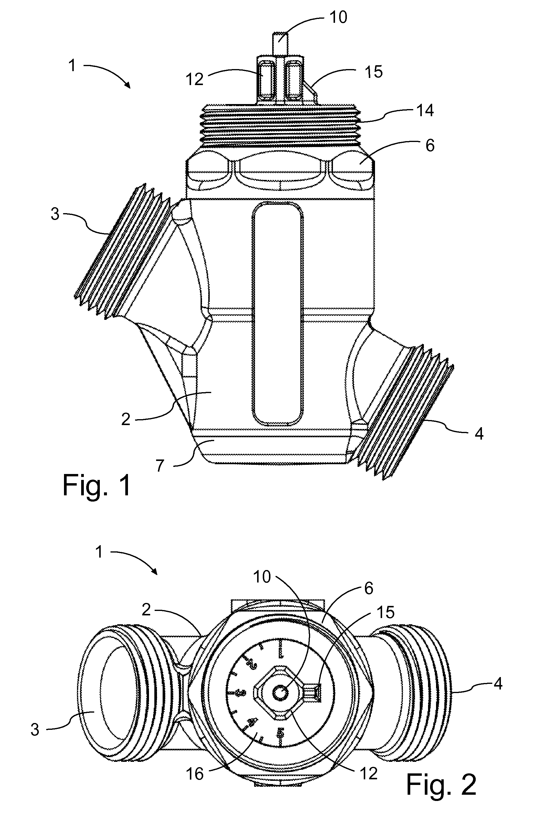
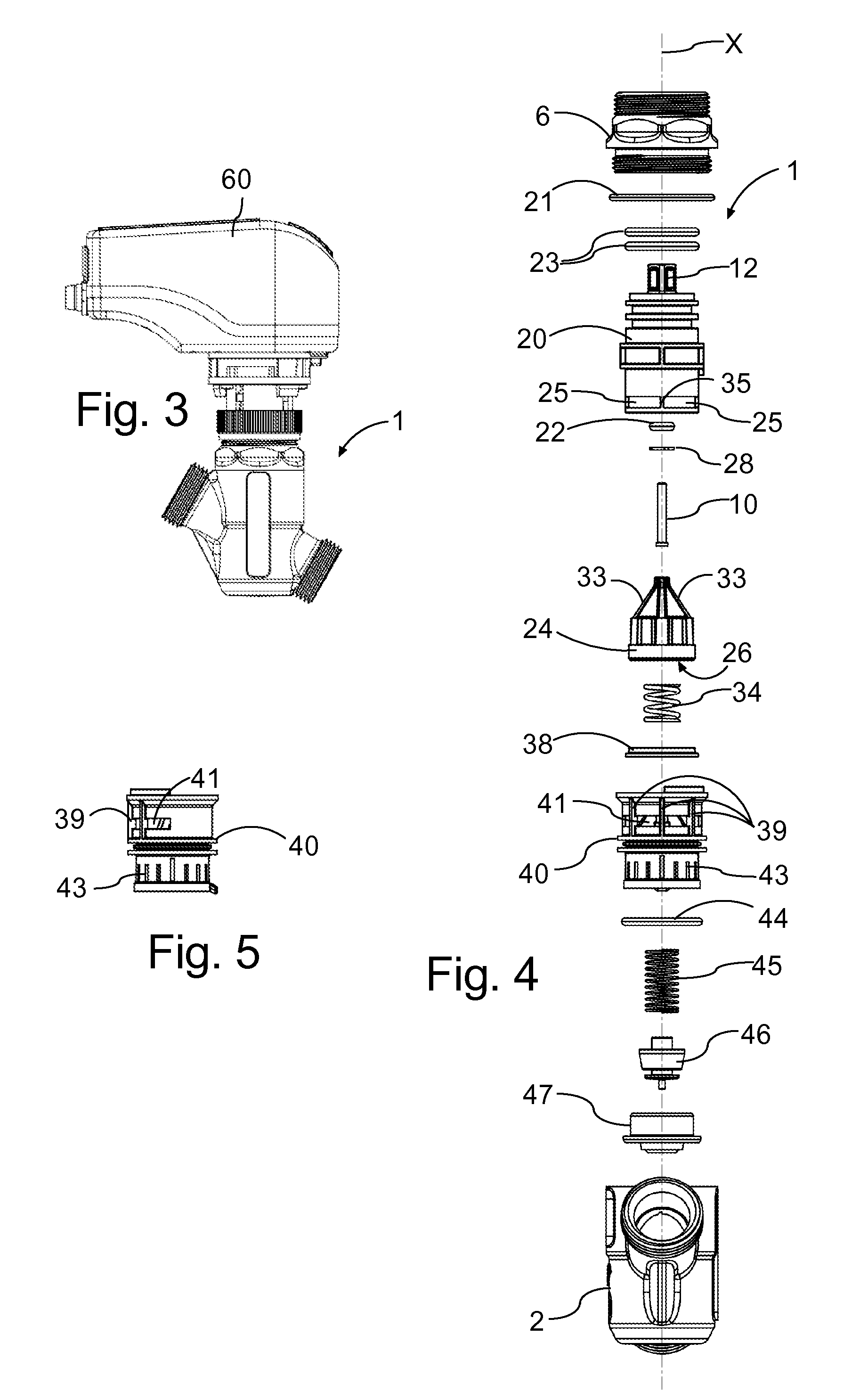
[0039]The control valve 1 is in an example embodiment of a regulator valve that includes differential pressure regulating facilities and flow area regulating facilities. Preferably the control valve is provided with means for manually presetting a maximum flow through area and with means for automatically adjusting the flow through area within the preset maximum. The flow regulation is tightly connected with the differential pressure regulation. Thus, the actual regulation in the parts referred to as the flow regulation facilities or the flow regulator is “only” a regulation of the size of the through-flow area. The combination of the carefully controlled through-flow area and the differential pressure across it, results in the actual flow regulation.

[0040]FIGS. 1 to 7 illustrate an example embodiment of a control val...


PUM


Abstract

A control valve for controlling liquid flow in a heating and / or cooling installation. The control valve includes differential pressure regulating facilities and flow area regulating facilities. The control valve is provided with means for manually presetting a maximum flow through area and with means for automatically adjusting the flow through area within the preset maximum.

Description

CROSS-REFERENCE TO RELATED APPLICATIONS[0001]This application claims the benefit of priority of Danish patent application No. PA2014 00015 filed on Jan. 10, 2014, the contents of which are incorporated herein by reference for all purposes.TECHNICAL FIELD[0002]The present inventions relate to a control valve for controlling liquid flow in a heating and / or cooling installation, in particular a control valve with a flow area regulator for regulating a flow area of at least one variable size entry opening and with a pressure regulating arrangement downstream of the flow area regulator with a pressure chamber between the flow area regulator and the pressure regulating arrangement.BACKGROUND ART[0003]WO 2013 / 007633 discloses a control valve for controlling liquid flow in a heating and / or cooling installation under command from an actuator. The control valve comprises a flow regulator with two annular valve members that have an axial overlap. The one valve member is manually rotatable rela...

Claims


Application Information

Patent Timeline
Patent Type & Authority Patents(United States)
IPC IPC(8): F16K39/02G05D7/01
CPCF16K39/026G05D7/0113G05D16/0641G05D16/028
Inventor IBSEN, BJARNE WITTENDORFFMOLLER, CARSTEN ENOELORENZEN, LASSE VESTERGAARDBOJGAARD, MILLE SVEJE
Owner FLOWCON INT
Why Eureka
Try Eureka