Piston cooling apparatus

a technology for internal combustion engines and cooling apparatuses, which is applied in the direction of machines/engines, separation processes, filtration separation, etc., can solve the problems of increasing the cost and size of the cooling apparatus, increasing the cost, and complicated maintenance work, so as to facilitate mounting and removal, simplify the structure, and facilitate the effect of fixing

Active Publication Date: 2016-03-08
HONDA MOTOR CO LTD +1
View PDF3 Cites 4 Cited by
  • Summary
  • Abstract
  • Description
  • Claims
  • Application Information

AI Technical Summary

Benefits of technology

[0008]The invention is made in view of the above circumstances and thus it is an object of the invention to provide a piston cooling apparatus which can simplify a filter fixing structure, is not complicated in structure, can facilitate the mounting and removal thereof, and can facilitate the maintenance work thereof.

Problems solved by technology

Therefore, the maintenance work is complicated.
Thus, the structure of the main body tends to be complicated, thereby raising a possibility that the cost and size of the cooling apparatus can be increased.
In this case, however, when maintaining the cooling apparatus, the whole of the cooling apparatus must be replaced, thereby causing the cost to increase.
Thus, for example, when a relatively large foreign substance is trapped by the filter, there is a fear that such substance can close the bottom greatly.
Also, the formation of the uneven shape in the bottom can enhance the rigidity of the bottom and thus the strength thereof such that it is hard to deform when it is contacted with the filter or when it receives oil pressure.
Also, since the filter will not be removed from the main body unless it is rotated, in a state where the main body is mounted on the internal combustion engine, the filter is hard to be removed from the main body.

Method used


Image

  • Piston cooling apparatus
  • Piston cooling apparatus
  • Piston cooling apparatus

Examples


first embodiment

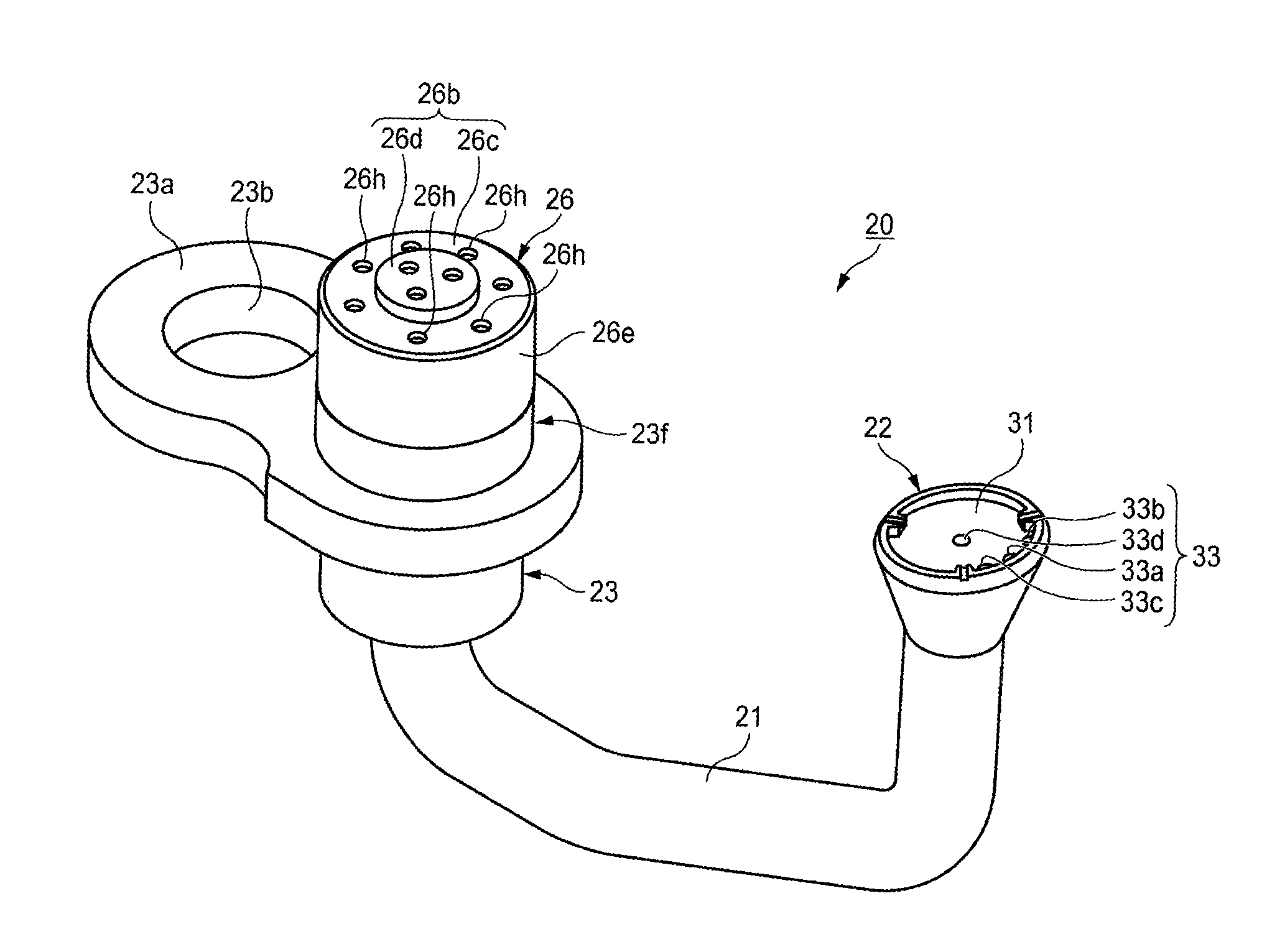
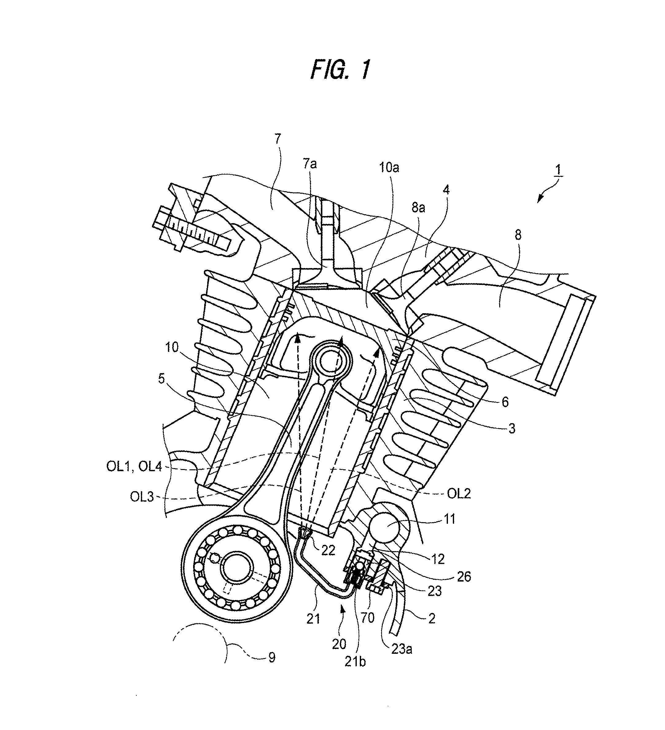
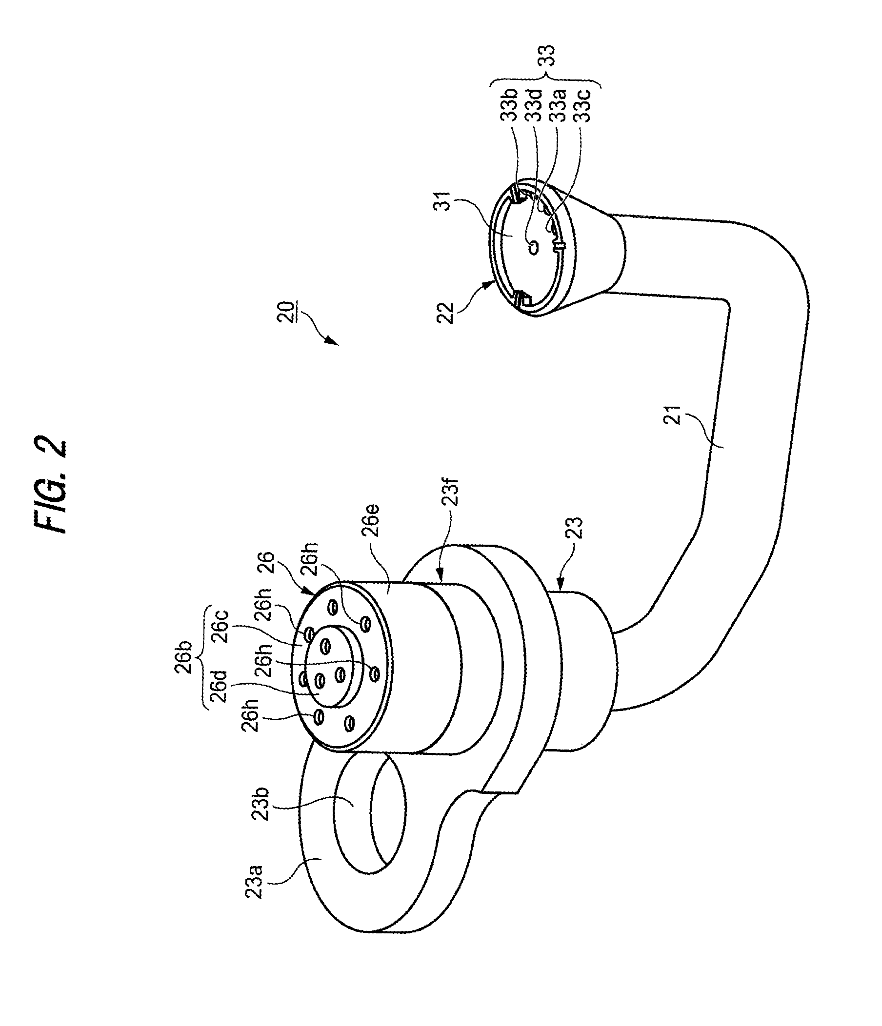
[0038]In a first embodiment of the invention, description is given specifically of an apparatus for cooling a piston of an internal combustion engine applied to a motorcycle as an example of a saddle type vehicle with reference to FIGS. 1 to 6. Here, directions such as vertical and horizontal directions in this specification are defined as directions obtained when the accompanying drawings are viewed according to the reference numerals and signs of the specification.

[0039]In an internal combustion engine 1 according to this embodiment, as shown in FIG. 1, a cylinder bore 10 is defined by a cylinder 3 and a cylinder head 4 respectively disposed above a crank case 2. To a piston 6 movable vertically within the cylinder bore 10, from behind, there is connected a connecting rod 5 which is connected to a crankshaft 9.

[0040]Here, a suction port 7 and an exhaust port 8 are connected to a combustion chamber 10a surrounded by the upper surface of the piston 6 and cylinder bore 10, whereby su...

second embodiment

[0066]Now, description is given below of a second embodiment with reference to FIG. 8.

[0067]In a piston cooling apparatus 20B according to the second embodiment of the invention, while the illustration and description of the same structures of the apparatus 20B as the above-mentioned first embodiment are omitted, there are illustrated only the structures thereof and their peripheral structures different from the first embodiment. Here, FIG. 8 is an exploded perspective view of the piston cooling apparatus 20B of the second embodiment.

[0068]The filter 26B of the piston cooling apparatus 20B shown in FIG. 8, similarly to the first embodiment, has a bottomed cylindrical shape. However, in this embodiment, a female screw section 26j is formed in the inner surface of outer peripheral portion 26e. On the other hand, in the main body 23, a male screw section 23j is formed in the outer wall portion 26e. When the male screw portion 23j and female screw portion 26j are threadedly engaged with...

third embodiment

[0071]Now, description is given below of a third embodiment of the invention with reference to FIG. 9.

[0072]In a piston cooling apparatus 20C according to the third embodiment of the invention as well, while the illustration and description of the same structures of the apparatus 20C as the above-mentioned first embodiment are omitted, there are illustrated only the structures thereof and their peripheral structures different from the first embodiment. Here, FIG. 9 is an exploded perspective view of the piston cooling apparatus 20C of the third embodiment.

[0073]As shown in FIG. 9, the filter 26C of the piston cooling apparatus 20C, similarly to the first embodiment, has a bottomed cylindrical shape. However, in this embodiment, inside the outer peripheral portion 26e, there are disposed a pair of engaging pieces 26t which respectively project in a direction crossing an axial line CL. Also, the main body 23 includes in its outer wall portion 23f a pair of engaging groove portions 23g...


PUM

PropertyMeasurementUnit
angleaaaaaaaaaa
diameteraaaaaaaaaa
cylindrical shapeaaaaaaaaaa

Abstract

A piston cooling apparatus includes: a main body including a communication passage communicating with an oil path formed in an internal combustion engine; a nozzle pipe portion including an oil injection port configured to inject oil having passed through the communication passage toward a piston; and a filter disposed upstream of the nozzle pipe portion on the flow passage of the oil and including a hole having a smaller diameter than the minimum diameter of the oil injection port, the oil being injected toward the piston from the oil injection port, wherein: the filter is removably mounted on the outer surface of the outer wall portion of the main body existing upstream on the oil flow passage; and the main body is mounted on the internal combustion engine in a state where at least a portion of the filter is inserted into the oil path.

Description

BACKGROUND[0001]1. Field of the Invention[0002]The invention relates to an apparatus for cooling a piston of an internal combustion engine and, specifically, to an apparatus for cooling a piston by injecting oil from the back surface of the piston.[0003]2. Description of the Related Art[0004]Conventionally, as an apparatus for cooling a piston of an internal combustion engine, there is known an apparatus structured such that a nozzle pipe for forming a cooling oil flow passage in communication with an oil path formed within the internal combustion engine is extended toward the back surface of the piston and oil is injected from this nozzle pipe.[0005]This conventional technology, for example, JP-UM-A-S54-164328 provides an integrated structure that a filter is provided within an oil chamber in the main body of a cooling apparatus removably mounted on an internal combustion engine and a nozzle pipe is disposed downstream of the filter. Thus, the filter within the main body is used to...

Claims


Application Information

Patent Timeline
Patent Type & Authority Patents(United States)
IPC IPC(8): F02B75/00F01P3/08F01M1/08B01D35/00F01P3/10F02F1/22F02B75/02F02F3/20F01P1/04
CPCF01P3/10B01D35/005F01M1/08F01P3/08F01P1/04F02B2075/025F02F1/22F02F3/20
Inventor GOKAN, YOSHITSUGUKOBAYASHI, TOMOKAZUOSAKO, TAKAYUKIITO, MASATOSHINISHIMURA, KENICHIYAMAMOTO, KEIJISABATO, MASAKI
Owner HONDA MOTOR CO LTD
Why Eureka
Try Eureka