
Small anode germanium (SAGe) well radiation detector system and method

a germanium detector and small anode technology, applied in the field of radiation detection systems and methods, can solve the problems of reducing the energy resolution of germanium detectors, affecting the overall measurement efficiency, and affecting the detection efficiency of ionizing radiation, and achieves the effect of increasing capacitance and small capacitan

Active Publication Date: 2016-02-23
CANBERRA IND INC
View PDF13 Cites 2 Cited by
  • Summary
  • Abstract
  • Description
  • Claims
  • Application Information

AI Technical Summary

Benefits of technology

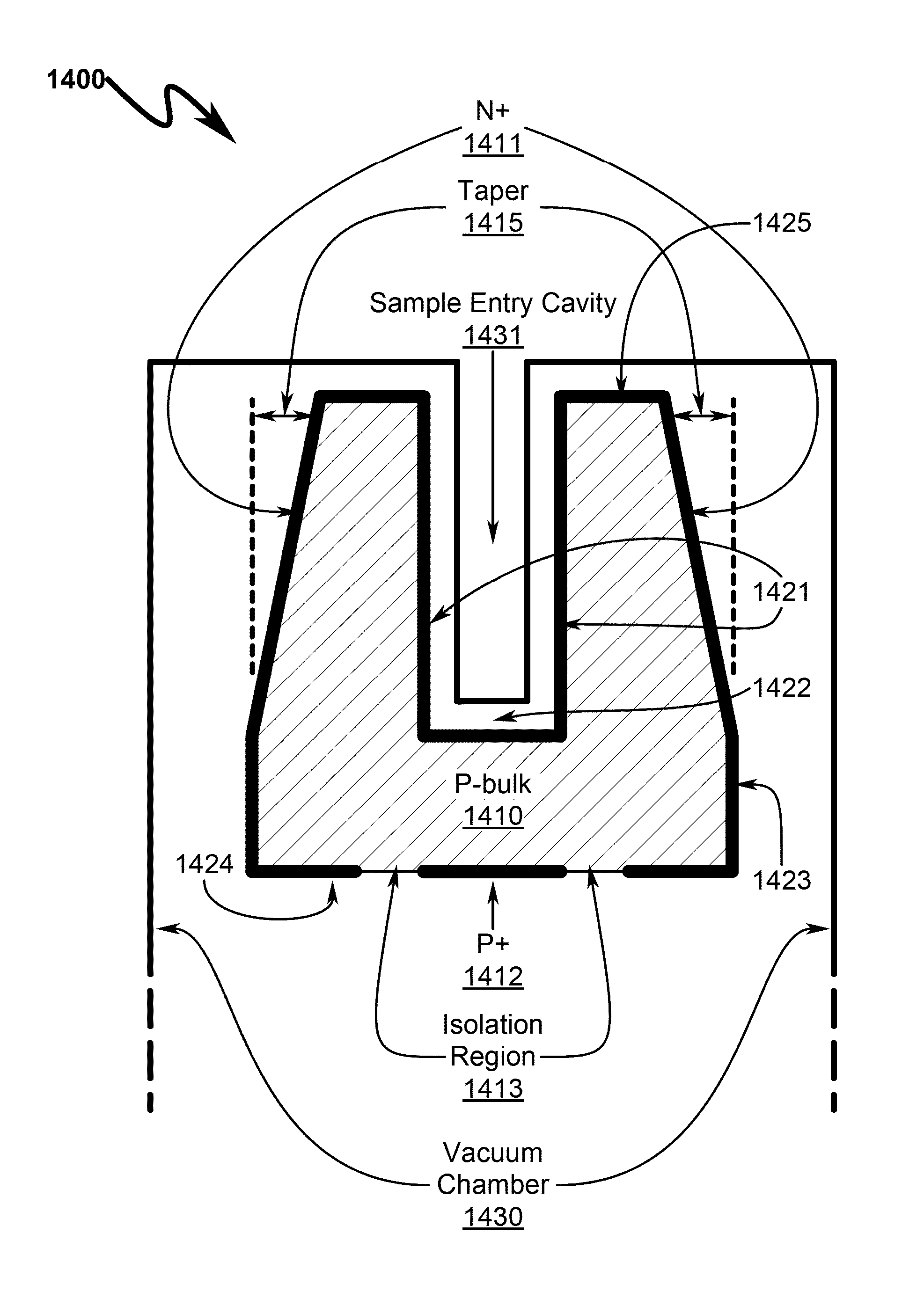
The patent describes a new system and method for detecting radiation in a SAGe well. The invention has three main benefits: it reduces the detector's capacitance, it reduces electronic noise, and it allows for shorter electrical connection lead lengths. By placing the signal contact on the bottom of the detector and using an electrode structure that minimizes capacitance, the system can accommodate larger samples while maintaining better energy resolution than conventional well detectors. Overall, the invention improves the accuracy and reliability of SAGe well detection.

Problems solved by technology

Otherwise, leakage current induced noise destroys the energy resolution of the germanium detector.
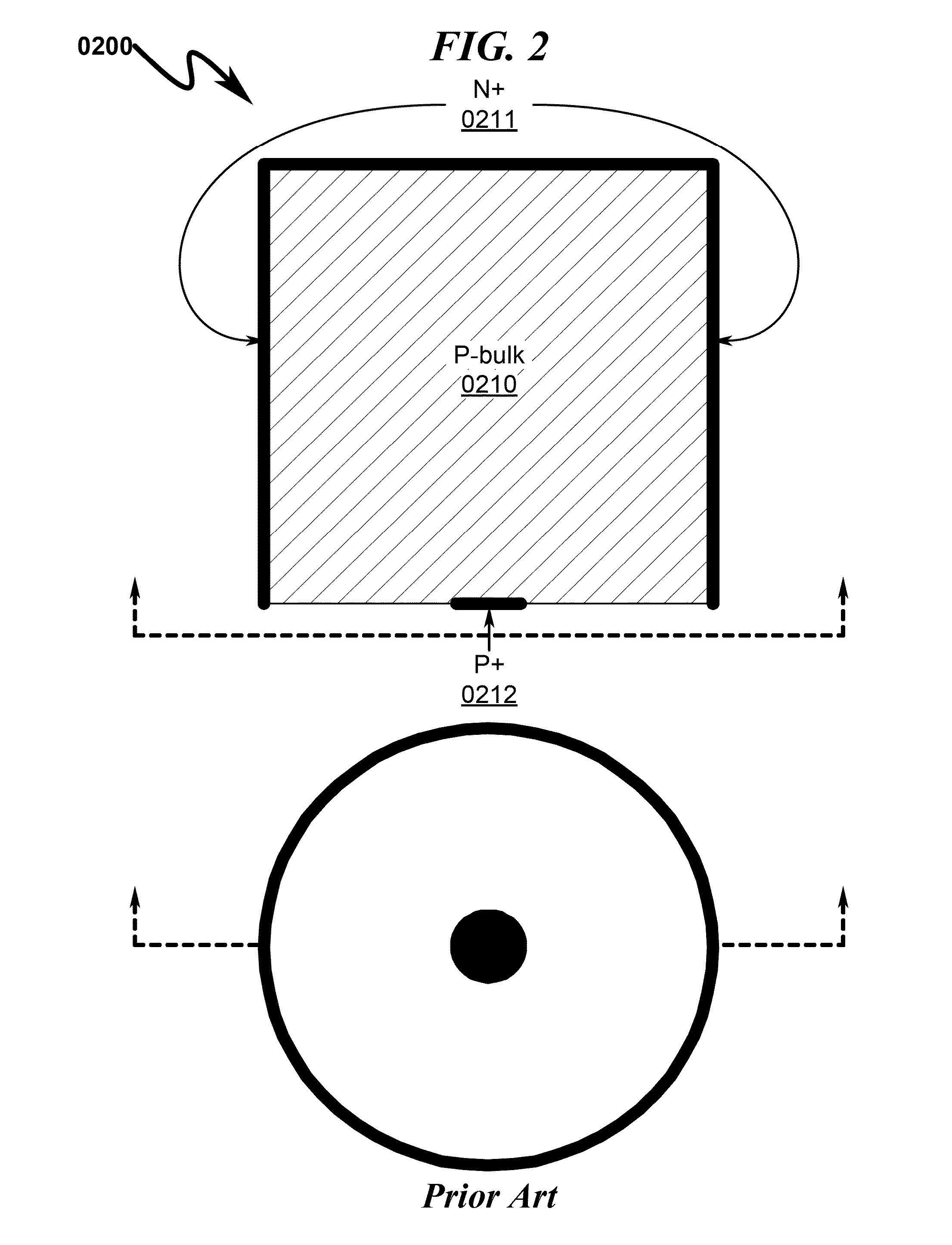
Although the volume of the detector may be large, the overall measurement efficiency is limited by the solid angle subtended by the detector surface (0210) facing the radiation source.
If the well is enlarged there is an attendant increase in the capacitance and this leads directly to increased electronic noise and a loss of resolving power (energy resolution).
This fundamental behavior of the conventional germanium well detector has long limited its usefulness, in part because the increase in noise is most damaging at low energies where the well detector is most advantageous.
This increase in diameter of the P+ electrode lining the hole results in an increase in device capacitance and hence an increase in noise.
Due to the front-end placement of the P+ electrode, the signal wire is lengthy and connection to the P+ electrode is complicated.
This increases the required separation distance between the vacuum enclosure (0920) and the P-bulk material (0910) and may in some circumstances increase microphonic noise induced by the extended wire length.
This characteristic creates a significant negative impact on radiation measurements using this type of radiation detector.
As can be seen from this experimental data, the performance of traditional well detectors suffers in comparison to other types of radiation detectors in part because large well diameters translate to increased detector capacitance and noise which reduce the effective detector resolution.
However, for applications where small, low-activity samples must be measured, this high counting efficiency of well detectors results in lower detection limits or shorter counting times to achieve a given detection limit.
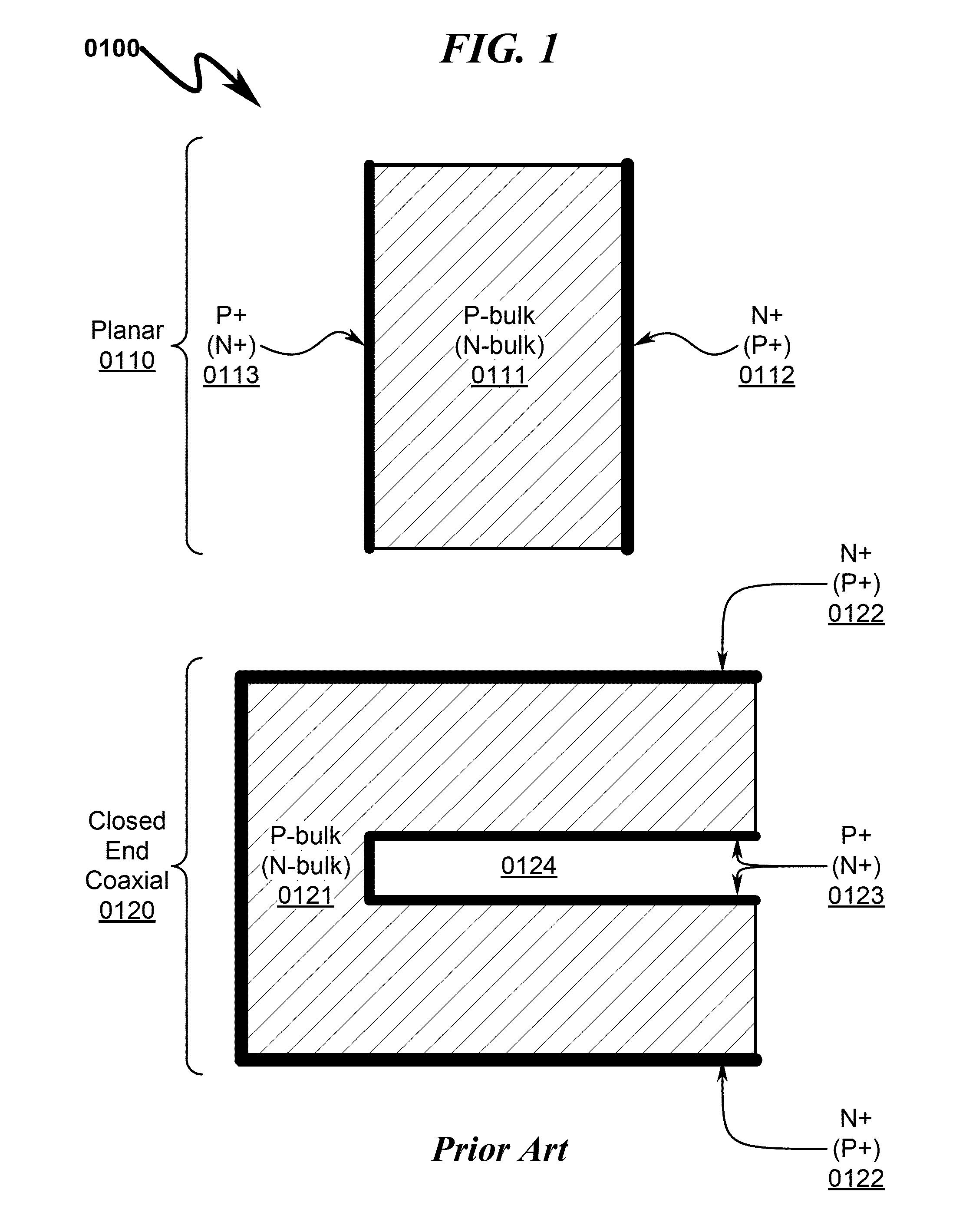
If more sample material is available another measurement geometry using a coaxial or planar detector may yield a lower MDA per gram of sample.Due to the higher capacitance of the detector and the consequently higher electronic noise, the resolution performance of well type detectors is worse than coaxial detectors, particularly at low energies.Because the sample is very close to the detector and completely surrounded by it, a well detector is more prone to summing effects, especially when isotopes with many coincident gammas are measured.Measured noise increases as the well diameter is increased.
Existing prior art well detectors also have other deficiencies that intrinsically decrease their performance in a variety of applications, as detailed below.
While the prior art as detailed above is currently used to form Ge well detectors, this prior art suffers from the following deficiencies:Prior art well detectors have high capacitance due to their large P+ contact areas.
To date the prior art has not fully addressed these deficiencies.

Method used


Image

  • Small anode germanium (SAGe) well radiation detector system and method
  • Small anode germanium (SAGe) well radiation detector system and method
  • Small anode germanium (SAGe) well radiation detector system and method

Examples


embodiment

Preferred Embodiment Method Summary

[0178]The present invention preferred exemplary method embodiment anticipates a wide variety of variations in the basic theme of implementation, but can be generalized as a SAGe well radiation detector method, the method operating in conjunction with a SAGe well radiation detector system, the system comprising:[0179](a) P-type bulk germanium volume (PGEV);[0180](b) N+ electrode;[0181](c) P+ electrode; and[0182](d) vacuum encapsulating chamber enclosure (VECE);[0183]wherein[0184]the PGEV further comprises an internal surface and an external surface;[0185]the external surface comprises an outer surface, an external base region (EBR), and a cavity entry region (CER);[0186]the PGEV further comprises an internal well cavity void (IWCV), the surface of the IWCV forming the internal surface;[0187]the P+ electrode is formed on the EBR and surrounded by an isolation region;[0188]the N+ electrode is formed on the internal surface, the outer surface, the CER,...


PUM


Abstract

A small anode germanium well (SAGe well) radiation detector system / method providing for low capacitance, short signal leads, small area bottom-oriented signal contacts, enhanced performance independent of well diameter, and ability to determine radiation directionality is disclosed. The system incorporates a P-type bulk germanium volume (PGEV) having an internal well cavity void (IWCV). The external PGEV and IWCV surfaces incorporate an N+ electrode except for the PGEV external base region (EBR) in which a P+ contact electrode is fabricated within an isolation region. The PGEV structure is further encapsulated to permit operation at cryogenic temperatures. Electrical connection to the SAGe well is accomplished by bonding or mechanical contacting to the P+ contact electrode and the N+ electrode. The EBR of the PGEV may incorporate an integrated preamplifier inside the vacuum housing to minimize the noise and gain change due to ambient temperature variation.

Description

CROSS REFERENCE TO RELATED APPLICATIONS[0001]Not ApplicablePARTIAL WAIVER OF COPYRIGHT[0002]All of the material in this patent application is subject to copyright protection under the copyright laws of the United States and of other countries. As of the first effective filing date of the present application, this material is protected as unpublished material.[0003]However, permission to copy this material is hereby granted to the extent that the copyright owner has no objection to the facsimile reproduction by anyone of the patent documentation or patent disclosure, as it appears in the United States Patent and Trademark Office patent file or records, but otherwise reserves all copyright rights whatsoever.STATEMENT REGARDING FEDERALLY SPONSORED RESEARCH OR DEVELOPMENT[0004]Not ApplicableREFERENCE TO A MICROFICHE APPENDIX[0005]Not ApplicableFIELD OF THE INVENTION[0006]The present invention generally relates to systems and methods for the detection of radiation, more particularly, but...

Claims


Application Information

Patent Timeline
Patent Type & Authority Patents(United States)
IPC IPC(8): H01L31/117G01T1/29G01T1/167H01L31/08H01L31/075
CPCH01L31/117G01T1/167G01T1/2928H01L31/075H01L31/085Y02E10/548
Inventor YOCUM, KENNETH MICHAELCOLARESI, JAMES F.TENCH, ORREN K.
Owner CANBERRA IND INC
Learn More