
Aerostructure for rigid body airship

a rigid body, airship technology, applied in the direction of rigid airships, etc., can solve the problems of limited forward airspeed, cigar-shaped rigid airships with the disadvantage of excessive weight, and cigar-shaped hulls that are also inability to produce significant aerodynamic lift, etc., to achieve the effect of being sufficiently light and cost-effective to assembl

Active Publication Date: 2016-02-23
WORLDWIDE AEROS CORP
View PDF15 Cites 21 Cited by
  • Summary
  • Abstract
  • Description
  • Claims
  • Application Information

AI Technical Summary

Benefits of technology

The present invention is an airship hull that is lightweight and cost-effective to assemble. It includes a rigid internal frame, a semi-rigid membrane skin, and a rigid aeroshell frame which carries the aerodynamic pressure loads on the airship. The aeroshell is the primary pressure shell structure and is connected at multiple points to the internal frame. The aeroshell is the major external frame of the vehicle and protects it from damage. The design of the internal main frame allows for large bending moments and the skin may act as a lifting gas container or contain gas cells or bags. The technical effect of the invention is a practical lifting body airship hull that can be easily assembled and is lightweight and cost-effective.

Problems solved by technology

Conventional semi and non-rigid airships rely on internal pressure to maintain their form and therefore have limited forward airspeed because air pressure loads deform the nose of the hull.
Conventional cigar-shaped rigid airships have the disadvantages of excessive weight due to the frame carrying all of the bending moments and aerodynamic loads.
A cigar shaped hull is also unable to produce significant aerodynamic lift which further limits the payload capacity of the airship.
Moreover, all conventional airships have the disadvantage of requiring ballast for payload exchange and thus require a ground handling crew to ballast the airship upon landing, further limiting utility.
While rigid lifting body or hybrid airships have been proposed, to the inventors' knowledge, no such craft are presently operational.
These hulls however, if built, would likely prove so heavy as to render the designs nonfunctional much less practical for commercial or military use.

Method used


Image

  • Aerostructure for rigid body airship
  • Aerostructure for rigid body airship
  • Aerostructure for rigid body airship

Examples


Embodiment Construction

[0037]The present invention will now be described more fully hereinafter with reference in the accompanying drawings to the exemplary embodiment. The exemplary embodiment in this instance refers to a prototype airship hull developed by Worldwide Aeros Corp. and constructed by Aeros Aeronautical Systems Corp. both of Montebello, Calif. The invention may, however, may be embodied in many different forms and should not be construed as being limited to the prototype embodiment set forth herein. Rather the prototype embodiment is provided so that this disclosure will be thorough and complete, and will fully convey the scope of the invention to those skilled in the art. Like numbers refer to like elements throughout.

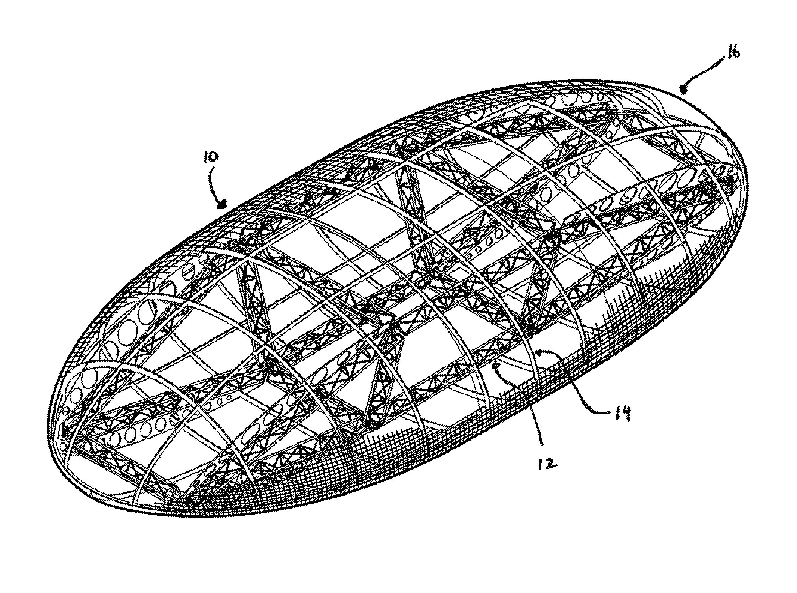
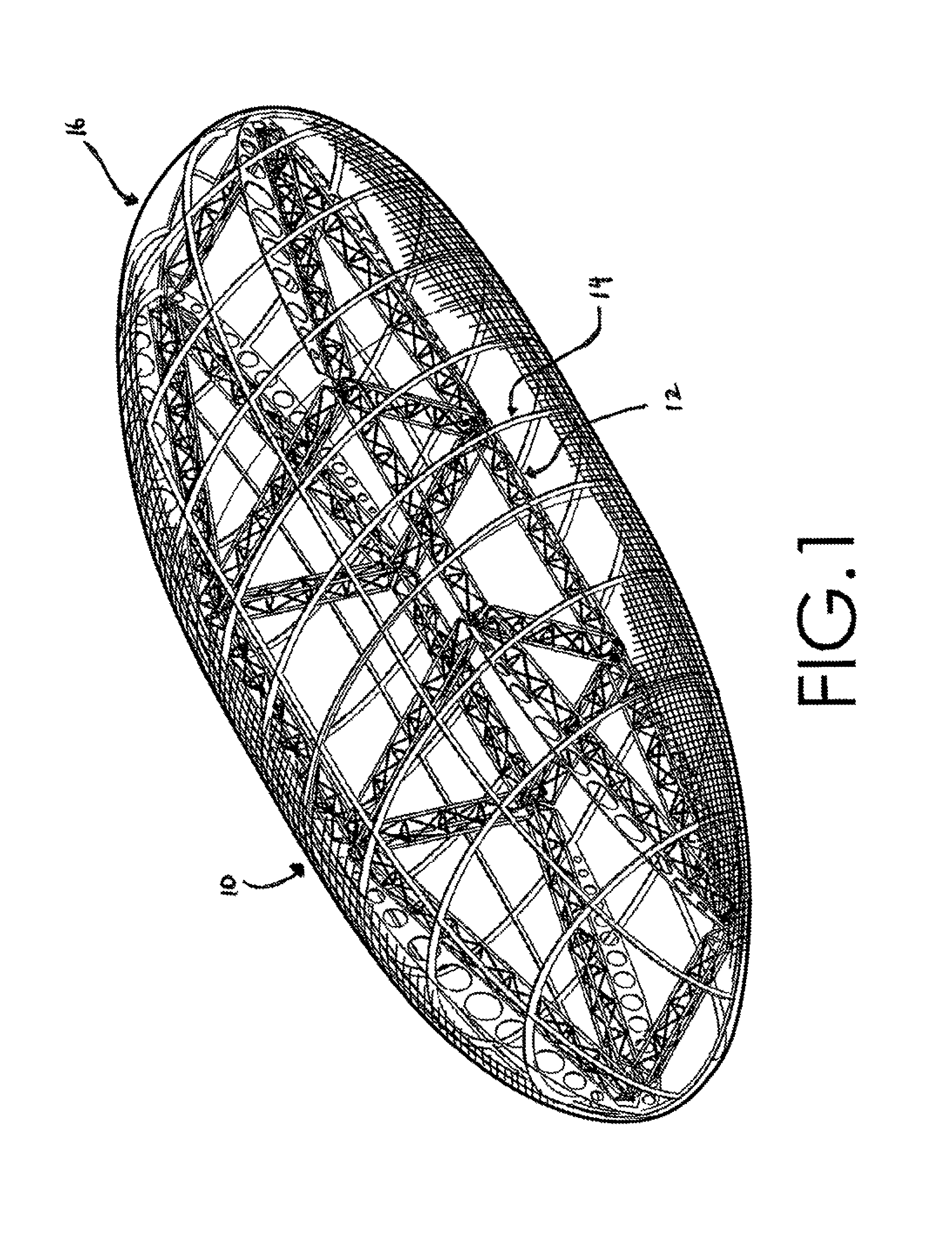
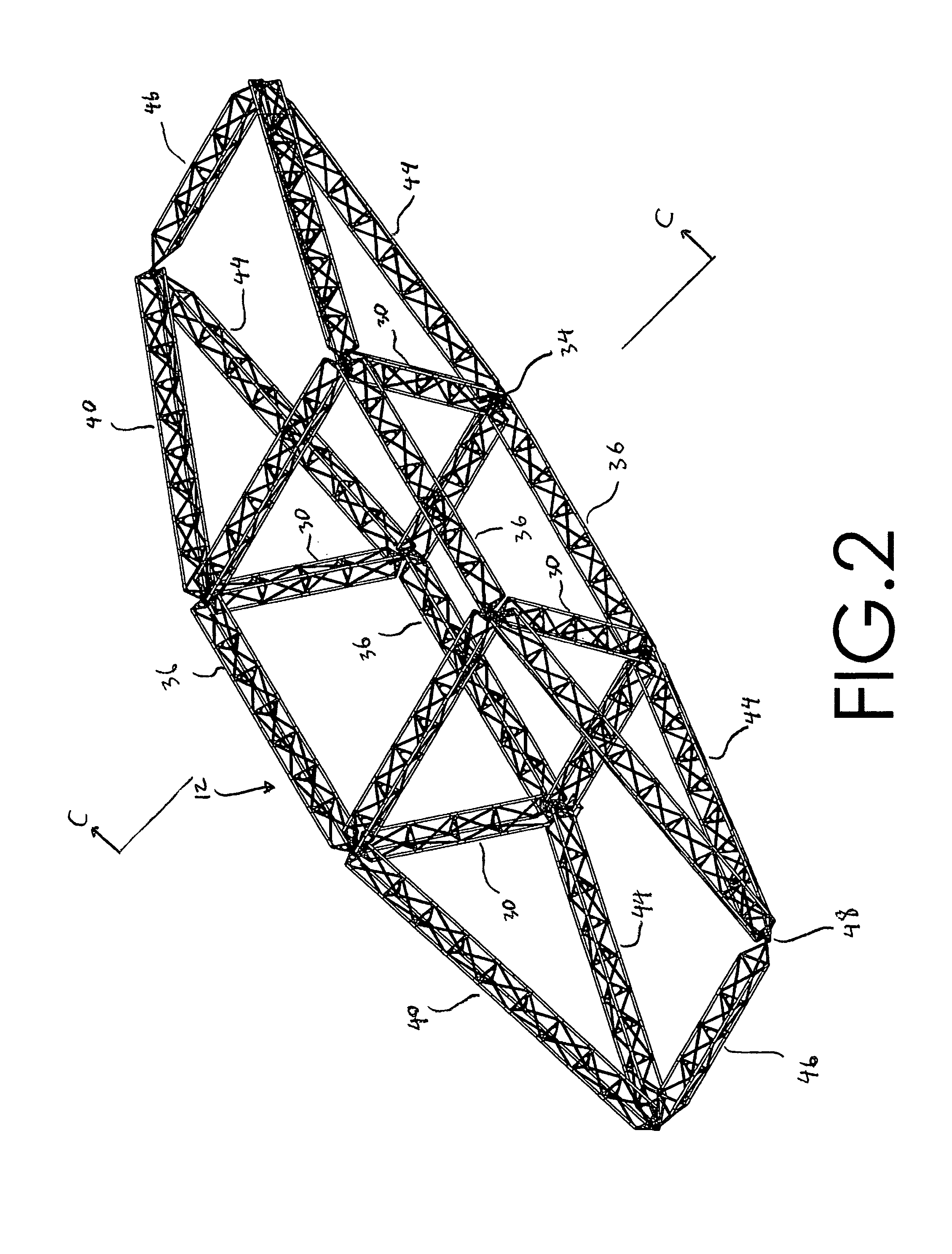
[0038]Referring now to FIGS. 1-6, FIG. 1 shows the airship hull 10 of the present invention. FIG. 2 depicts the internal or main frame assembly 12 of the airship hull 10. FIG. 3 depicts the aeroshell frame assembly 14 and FIG. 4 depicts the skin assembly 16 of the hull 10. The...


PUM


Abstract

An airship hull is provided that is sufficiently light and cost effective so as to make lifting body type airships practical vehicles for carrying people and cargo. The present invention hull design includes three main structural features, i.e., a rigid internal main frame which carries all primary moment and shear loads induced in the vehicle, the vehicle's skin which forms a semi-rigid barrier membrane for the lighter-than-air lifting gas, and a rigid aeroshell frame interposed between the main frame and the skin. The aeroshell frame and skin, in combination, are referred to as the aeroshell. The aeroshell carries the aerodynamic pressure loads induced on the airship.

Description

BACKGROUND OF THE INVENTION[0001]1. Field of the Invention[0002]The present invention relates generally to the field of airships or buoyant vehicles and, more particularly, to a lightweight, lift producing, airframe and shell structure (“hull”) for a rigid body airship. A lift producing hull is highly advantageous because it allows an airship to take off in a statically negative condition, i.e., in a condition where the hull and payload weight exceed the maximum buoyancy supplied by the lifting gas.[0003]2. Background of the Invention[0004]Airships generate buoyant lift by displacing the surrounding air with a hull containing a lighter than air gas. Generally, there are three conventional types of airships, i.e., rigid, semi-rigid, and non-rigid designs. Most commonly, conventional airships have featured a cigar shaped hull, i.e., an elongated hull of circular cross-section. The conventional rigid airship uses a hull having an internal framework supported by multiple gas bags or cel...

Claims


Application Information

Patent Timeline
Patent Type & Authority Patents(United States)
IPC IPC(8): B64B1/08B64B1/06
CPCB64B1/08B64B1/06
Inventor PASTERNAK, IGORNEMIROVSKY, EUGENEKOUCHAK, MANSOOR
Owner WORLDWIDE AEROS CORP
Learn More