
Automatic construction of deadlock free interconnects

a deadlock-free, interconnect technology, applied in the direction of digital transmission, data switching networks, instruments, etc., can solve the problems of complex routing, low interconnect resource cost, and large number of components on the chip, so as to keep the cost of interconnect resources low

Active Publication Date: 2016-01-26
INTEL CORP
View PDF94 Cites 27 Cited by
  • Summary
  • Abstract
  • Description
  • Claims
  • Application Information

AI Technical Summary

Benefits of technology

This patent proposes an automatic way to create a system interconnect that avoids deadlocks at both the network and application levels. It does this by creating a low-cost interconnection based on the specified message patterns between different components of the system. An example of how to achieve this is also provided.

Problems solved by technology

The number of components on a chip is rapidly growing due to increasing levels of integration, system complexity and shrinking transistor geometry.
This form of routing may be complex to analyze and implement and is therefore rarely used in practice.
Software applications running on large multi-core systems can generate complex inter-communication messages between the various blocks.
Such complex, concurrent, multi-hop communication between the blocks can result in deadlock situations on the interconnect.
Deadlock occurs in a network when messages are unable to make progress to their destination because they are waiting on one another to free up resources (e.g. at buffers and channels).
Deadlocks due to blocked buffers can quickly spread over the entire network, which may paralyze further operation of the system.
Network end points may not be ideal sinks, i.e. they may not consume all incoming packets until some of the currently outstanding packets are processed.
Such a multi-point sequence of intercommunication may introduce complex dependencies resulting in protocol level deadlock.
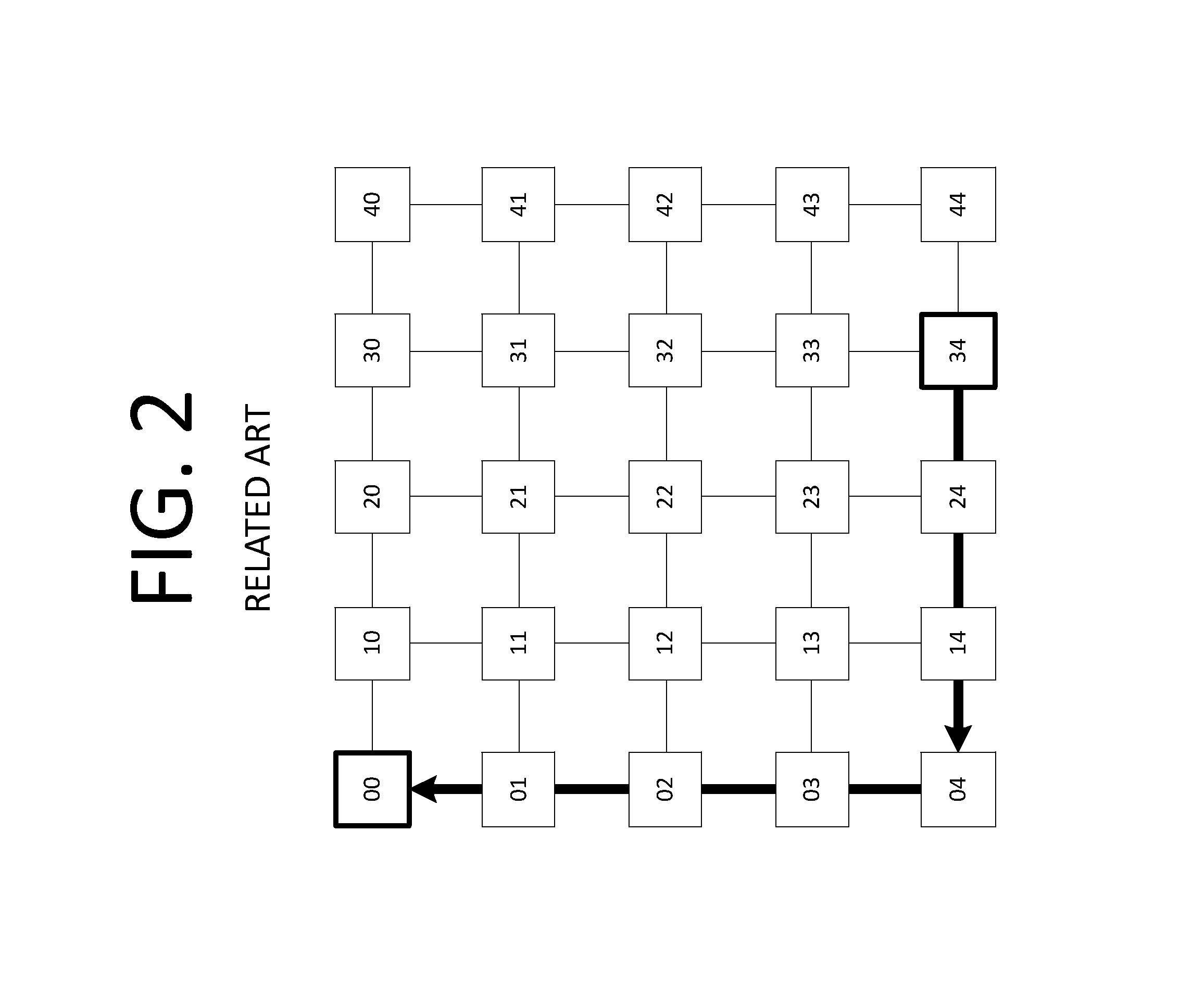
Independent messages from one end point to another on the network will not cause protocol level deadlocks; however, depending on the routing of such messages on the network, network level deadlocks are still possible in the system.
However the refill data is blocked behind this request ‘3’.
However such complex mechanisms are too expensive in terms of power, area and speed to implement on interconnection networks where the primary demands are low latency and high performance.

Method used


Image

  • Automatic construction of deadlock free interconnects
  • Automatic construction of deadlock free interconnects
  • Automatic construction of deadlock free interconnects

Examples


Embodiment Construction

[0032]Complex dependencies introduced by applications running on large multi-core systems can be difficult to analyze manually to ensure deadlock free operation. Example embodiments described herein are based on the concept of automatically constructing deadlock free interconnect for a specified inter-block communication pattern in the system. An example process of the automatic deadlock free interconnect construction is also disclosed.

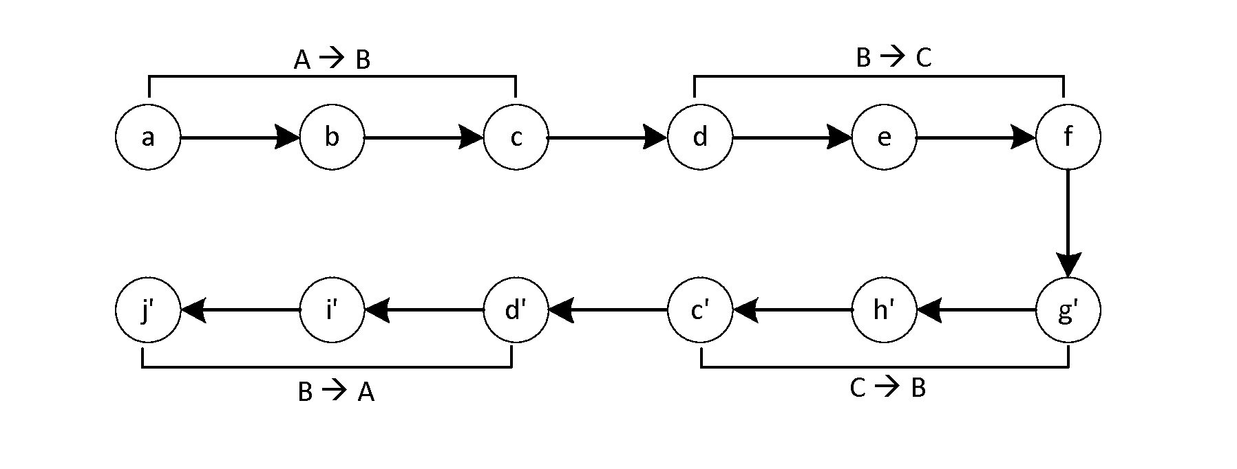
[0033]Applications running on multi-core systems often generate several sequences of inter-dependent messages between multiple blocks, wherein a message arriving at a block must generate another message for a different block, before it completes processing and releases the resources at the block for new messages. For a hypothetical example, consider a task running on block A which requests an operation to be performed on block B. On receiving the request message, block B completes part of the operation and sends partial results to a third block C whic...


PUM


Abstract

Systems and methods for automatically building a deadlock free inter-communication network in a multi-core system are described. The example embodiments described herein involve deadlock detection during the mapping of user specified communication pattern amongst blocks of the system. Detected deadlocks are then avoided by re-allocation of channel resources. An example embodiment of the deadlock avoidance scheme is presented on Network-on-chip interconnects for large scale multi-core system-on-chips.

Description

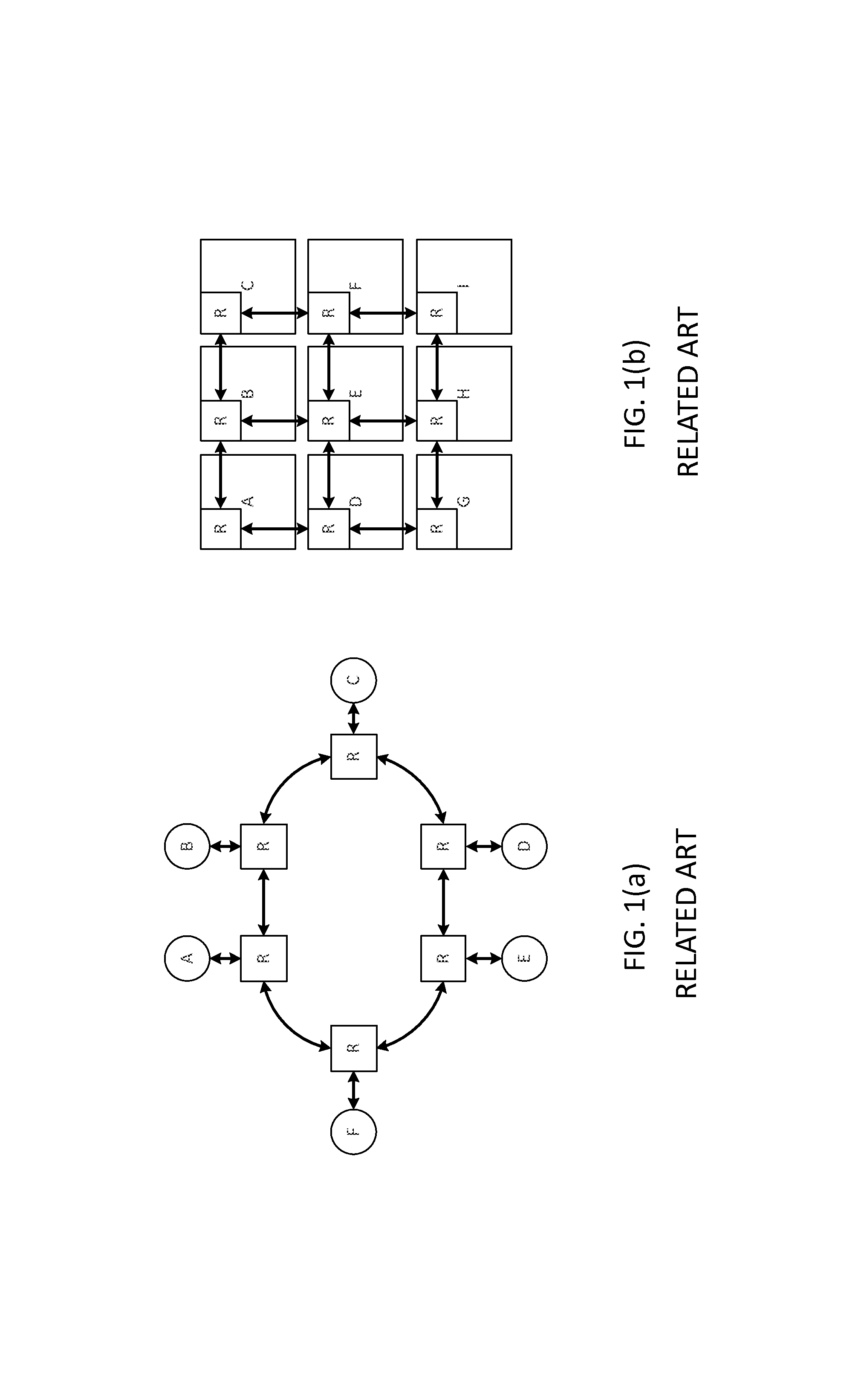
BACKGROUND[0001]1. Technical Field[0002]Methods and example embodiments described herein are generally directed to interconnect architecture, and more specifically, to network on chip system interconnect architecture.[0003]2. Related Art[0004]The number of components on a chip is rapidly growing due to increasing levels of integration, system complexity and shrinking transistor geometry. Complex System-on-Chips (SoCs) may involve a variety of components e.g., processor cores, DSPs, hardware accelerators, memory and I / O, while Chip Multi-Processors (CMPs) may involve a large number of homogenous processor cores, memory and I / O subsystems. In both systems the on-chip interconnect plays a key role in providing high-performance communication between the various components. Due to scalability limitations of traditional buses and crossbar based interconnects, Network-on-Chip (NoC) has emerged as a paradigm to interconnect a large number of components on the chip. NoC is a global shared co...

Claims


Application Information

Patent Timeline
Patent Type & Authority Patents(United States)
IPC IPC(8): G06F13/36H04L12/721G06F15/78G06F15/173
CPCG06F15/17312G06F15/7825H04L45/06
Inventor PHILIP, JOJIKUMAR, SAILESHNORIGE, ERICHASSAN, MAHMUDMITRA, SUNDARI
Owner INTEL CORP
Learn More