
Vee manifold

a manifold and valve body technology, applied in the field of manifolds, can solve the problems of hardened mass not being able to pass through the corner, clogging of the wye manifold, and inability to clean easily by applying pressure, etc., and achieve the effect of convenient cleaning

Active Publication Date: 2016-01-26
ROOFTOP RES
View PDF44 Cites 13 Cited by
  • Summary
  • Abstract
  • Description
  • Claims
  • Application Information

AI Technical Summary

Benefits of technology

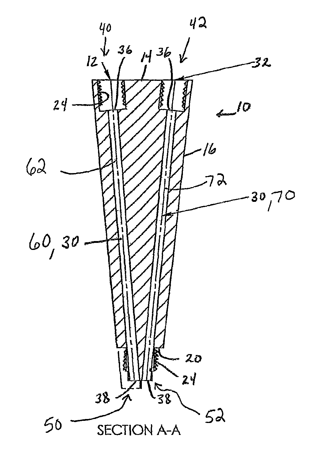
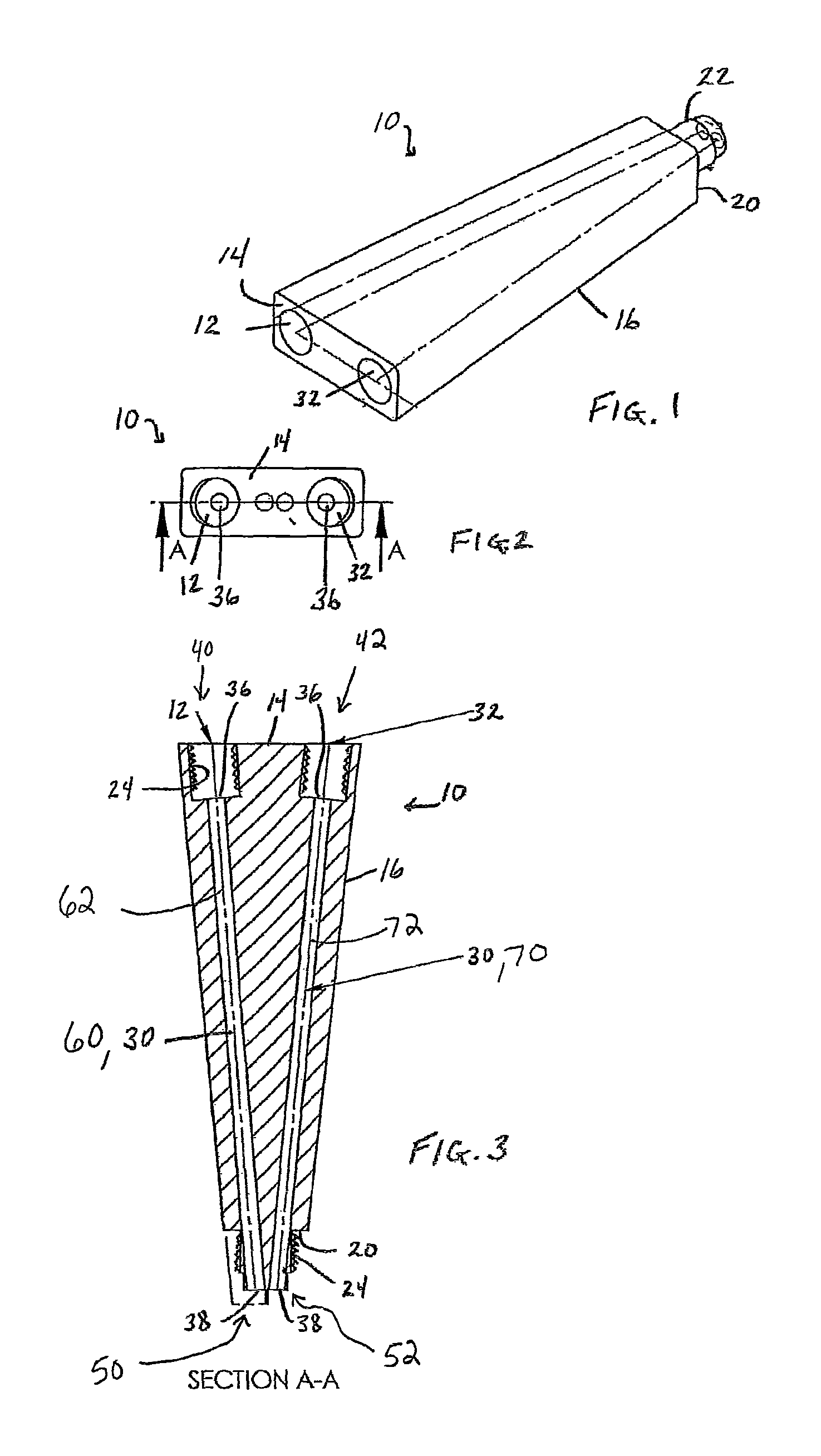
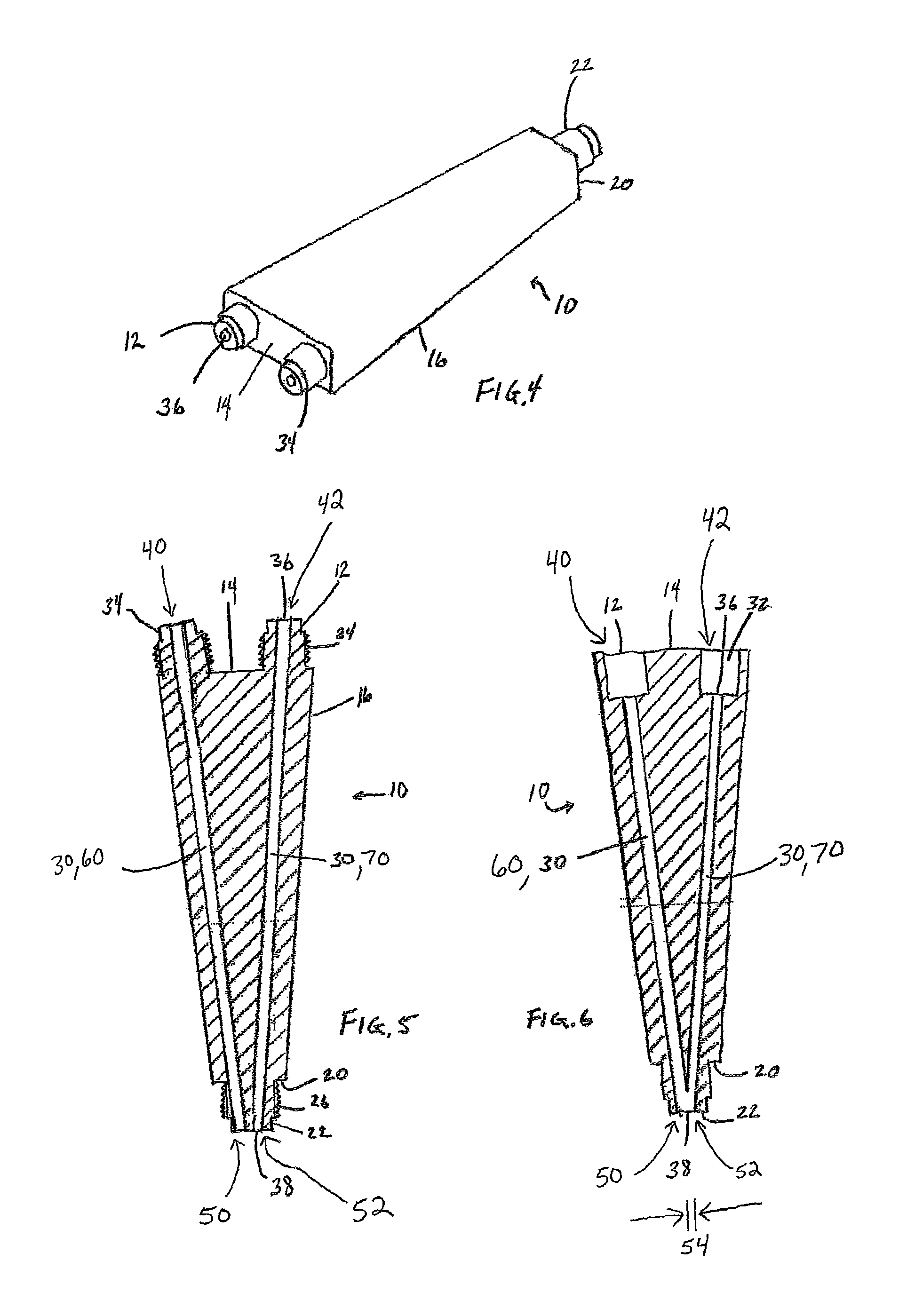
The present disclosure is about a manifold which has two sides and two channels that run from one side to the other. These channels have a longitudinal axis that is at an angle to the sides of the manifold. The purpose of the manifold is to make it easy to clean the channels. This is done by increasing the pressure of the substance that flows through the manifold or by using a tool to clean each channel once. In summary, the technical effect of this patent is to provide a manifold with channels that are easy to clean.

Problems solved by technology

In addition, when wye manifolds clog due to chemical reaction or physical change of the materials within, cleaning is not readily accomplished by applying pressure or by drilling due to the configuration of the internal pathways and the angles at which they are disposed within the manifold.
The curing process results in clogging as the physical state changes from that of a liquid to a solid or gel.
If pressure is applied in an attempt to dislodge this clog, the hardened mass cannot flow past the corner and the wye manifold is clogged.
It is not possible to eject this hardened mass by increasing the pressure of the fluids.
This process is not only time consuming but extremely messy, expensive, and wasteful as the liquid in the supply lines usually flows out and cannot be recovered.
This shut down procedure at the end of each use is quite time consuming and the grease has to be purged prior to the next start up.

Method used


Image

  • Vee manifold
  • Vee manifold
  • Vee manifold

Examples


Embodiment Construction

[0036]In the following detailed description, reference is made to the accompanying examples and figures that form a part hereof, and in which is shown, by way of illustration, specific embodiments in which the inventive subject matter may be practiced. These embodiments are described in sufficient detail to enable those skilled in the art to practice them, and it is to be understood that other embodiments may be utilized and that structural or logical changes may be made without departing from the scope of the inventive subject matter. Such embodiments of the inventive subject matter may be referred to, individually and / or collectively, herein by the term “invention” merely for convenience and without intending to voluntarily limit the scope of this application to any single invention or inventive concept if more than one is in fact disclosed. The following description is, therefore, not to be taken in a limited sense, and the scope of the inventive subject matter is defined by the ...


PUM


Abstract

A manifold having a first side, a second side, a first channel extending from the first side to the second side, and a second channel extending from the first side to the second side is disclosed. The first channel and the second channel each define a linear longitudinal axis. In one embodiment, the first channel longitudinal axis and the second channel longitudinal axis are oblique to the first side and the second side of the manifold. The manifold of the present disclosure provides channels that can be easily cleaned and allow for an increased flow performance.

Description

CROSS-REFERENCE TO RELATED APPLICATIONS[0001]This application claims priority to U.S. Provisional Patent Application Ser. No. 61 / 623,610, filed Apr. 13, 2012, the entire disclosure of which is hereby expressly incorporated by reference herein.BACKGROUND OF THE INVENTION[0002]1. Field of the Disclosure[0003]The present invention relates to an improved manifold for dispensing of multiple component adhesives and other liquids. More particularly, the present invention provides an improved manifold that is easily cleanable.[0004]2. Description of the Related Art[0005]The delivery of liquid materials through tubing, hoses, or pipes is simple and well known. Differing materials traveling concurrently through separate tubes are also common. It is frequently desirable for differing materials traveling through multiple tubes to converge into one tube. As liquids flow towards this point of convergence, the contour of the tube path will impact the flow performance of the liquid, increase or dec...

Claims


Application Information

Patent Timeline
Patent Type & Authority Patents(United States)
IPC IPC(8): B67D3/00B01F15/00B01F5/06B01F13/00B05C17/005
CPCB67D3/0058B01F5/0615B01F13/0027B01F15/00038B05C17/0052B05C17/00553Y10T137/87153Y10T137/87161B01F25/43141B01F33/50114B01F35/12B01F33/00A61B2017/00495B01F25/40B05C11/1002
Inventor BURNS, ROBERT, S
Owner ROOFTOP RES
Learn More