
Advanced elevated feed distribution apparatus and process for large diameter FCC reactor risers

a technology of fcc reactor and feed distribution apparatus, which is applied in the direction of liquid chemical processes, gas-gas reaction processes, liquid-gas reactions of thin-film type, etc., can solve the problems of low conversion and achieve the effect of low conversion

Active Publication Date: 2016-01-19
UOP LLC
View PDF24 Cites 4 Cited by
  • Summary
  • Abstract
  • Description
  • Claims
  • Application Information

AI Technical Summary

Benefits of technology

The text describes a study of a riser design used in chemical processes. The researchers found that the oil and dispersion media only penetrate the riser about 0.6 meters deep, which causes three distinct reaction zones. In the first zone, the oil is exposed to the catalyst for a longer time, resulting in more coke deposition and poorer catalyst-oil contact. In the second zone, the catalyst-oil contact is poor, leading to lower conversion. In the third zone, the hot catalyst is concentrated in the center of the riser, causing higher temperature and additional dry gas formation. These findings help improve the design of risers and optimize chemical processes.

Problems solved by technology

As a result of zone 2, the catalyst-oil contacting in the riser is poorer, resulting in lower conversion.

Method used


Image

  • Advanced elevated feed distribution apparatus and process for large diameter FCC reactor risers
  • Advanced elevated feed distribution apparatus and process for large diameter FCC reactor risers
  • Advanced elevated feed distribution apparatus and process for large diameter FCC reactor risers

Examples


example 1

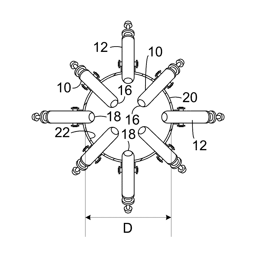
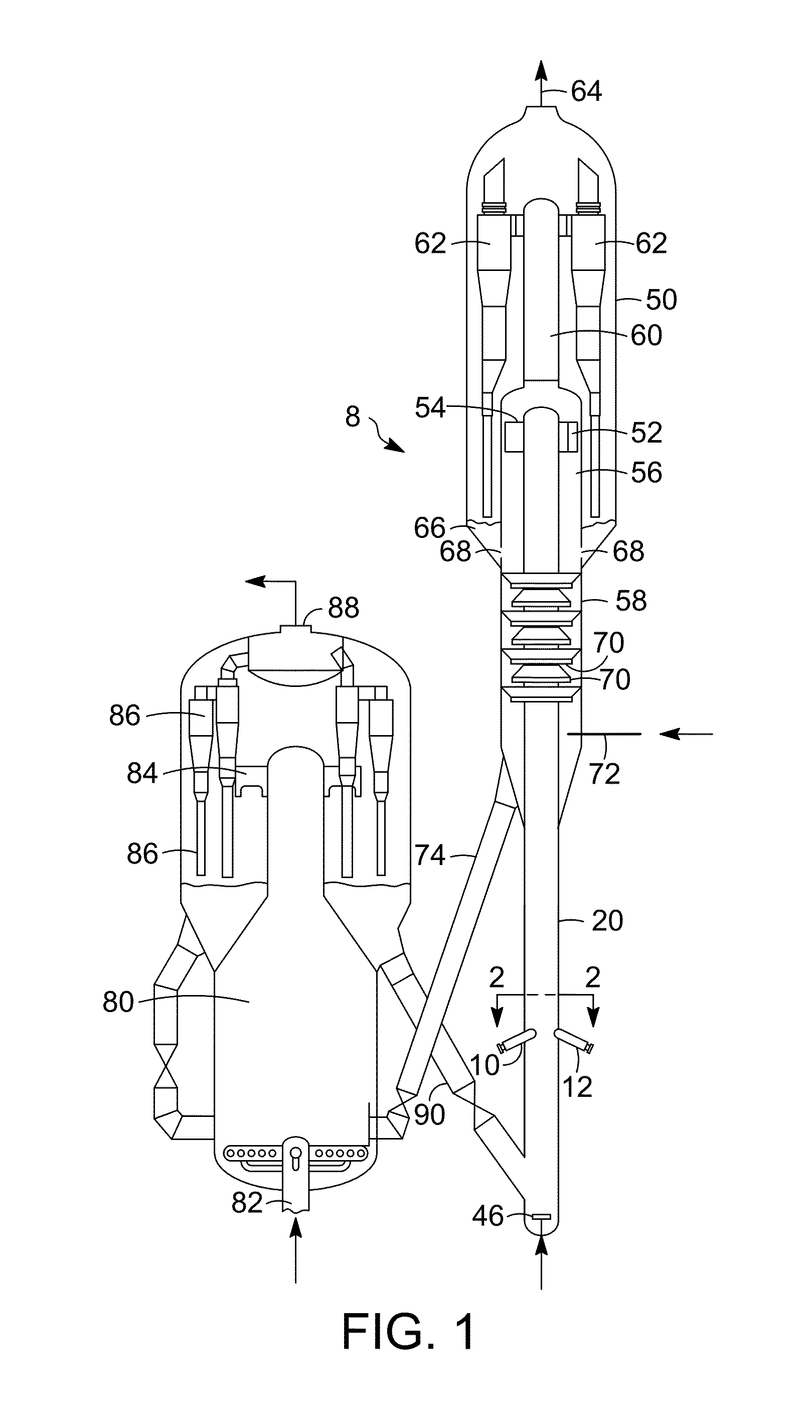
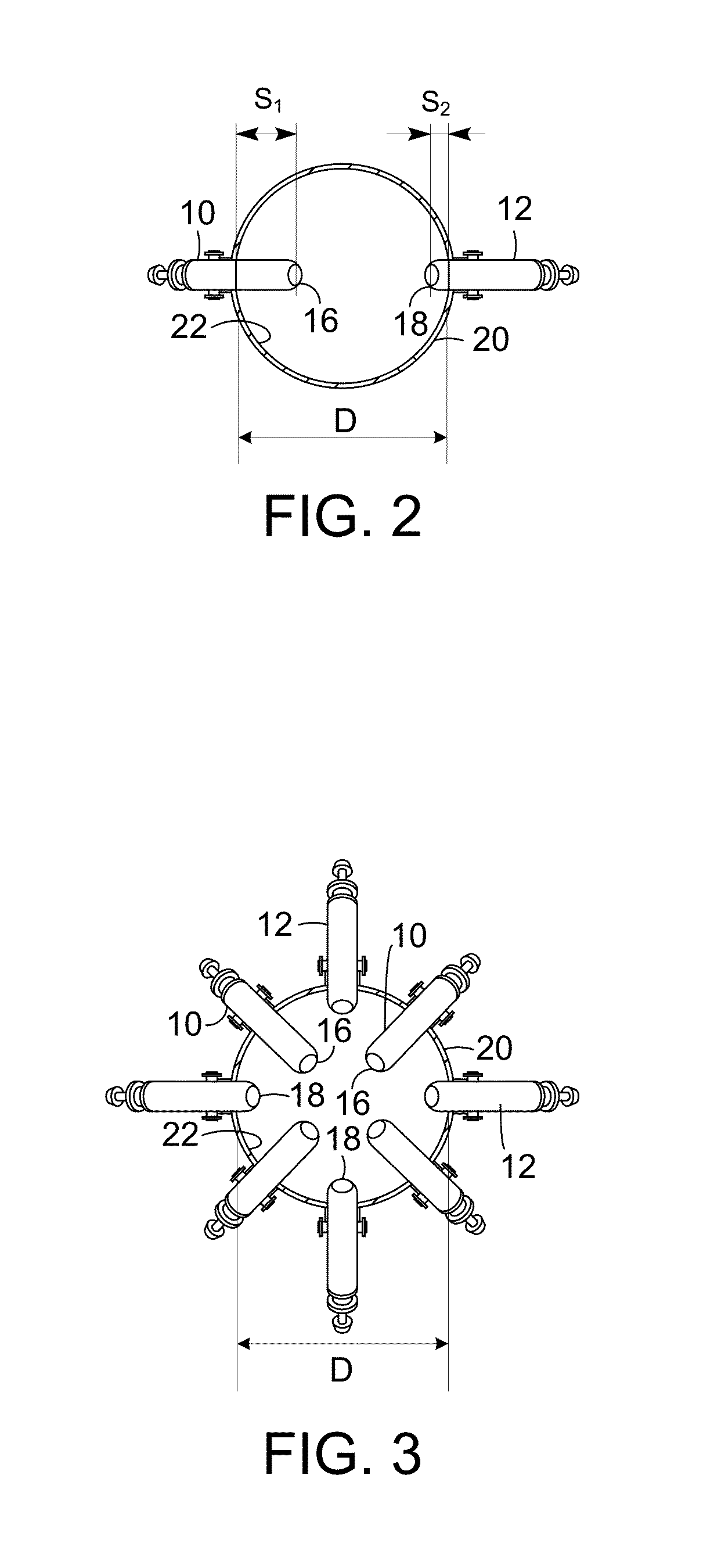
[0054]A commercially operating FCC unit with a capacity of 31,797,459 liters (200,000 barrels) per day was operating with poorer than expected yields and conversion. Conversion was 2-4 wt-% below the target, and dry gas yields were at 3.4 wt-% which was undesirably higher than the expected benchmark performance. The riser had an inner diameter of 2.2 m (6.6 ft) at the point of feed injection. The feed was injected through a series of feed distributors with equivalent radial penetrations circumferentially located around the periphery of the riser with tips about flush with the inner surface of the wall of the riser.

[0055]A computational fluid dynamics (CFD) model of the riser was created that would predict the catalyst density distribution in the riser downstream of the point of feed injection. The lift velocity was 2.8 m / s (9.2 ft / s) at just below the feed distributors. As shown in the plot in FIG. 10, the model indicated that a vapor annulus would be present at 1.5 m above the feed...

example 2

[0059]Gamma scans were completed on another riser with a conventional feed distribution arrangement on a different unit with an inner diameter of 1.6 m (5 ft) at the point of feed injection that was slightly smaller than the unit tested in Example 1. The first scan was completed with a lift velocity of 4.7 m / s (14 ft / s) in the lower riser section just below the feed distributors. No dense column of catalyst formed, but rather a very uniform catalyst density distributed across the riser at 2.5 m (8.1 ft) above the feed distributors as shown in FIG. 15. However, the second scan that was completed at a lower lift velocity of 3.3 m / s (10 ft / s) did indicate a vapor annulus and a high density column of catalyst had formed, indicated by the lighter region toward the center in FIG. 16. FIG. 16 was taken at 1.5 m (4.8 ft) above the feed distributors. It was not believed that the scan at 4.7 m / s need be taken at a lower elevation to match the elevation of the scan at 3.3 m / s because if an ann...


PUM

PropertyMeasurementUnit
inner diameteraaaaaaaaaa

Abstract

An FCC process and apparatus may include injecting hydrocarbon feedstock at different radial positions while at the same elevation inside a riser. Multiple distributors may be used to position the tips for injecting feedstock at multiple radial positions. The distributors with tips more deeply positioned in the riser will penetrate a dense catalyst column we discovered generates in risers of larger diameter over 1.3 meters.

Description

CROSS-REFERENCE TO RELATED APPLICATION[0001]This application claims priority from Provisional Application No. 61 / 305,766 filed Feb. 18, 2010, the contents of which are hereby incorporated by reference.BACKGROUND OF THE INVENTION[0002]This invention relates generally to a process for catalytic cracking of hydrocarbons.DESCRIPTION OF THE PRIOR ART[0003]Fluid catalytic cracking (FCC) is a catalytic conversion process for cracking heavy hydrocarbons into lighter hydrocarbons by bringing the heavy hydrocarbons into contact with a catalyst composed of finely divided particulate material in a fluidized reaction zone. Most FCC units use zeolite-containing catalyst having high activity and selectivity. As the cracking reaction proceeds, substantial amounts of highly carbonaceous material, referred to as coke, are deposited on the catalyst, forming spent catalyst. High temperature regeneration burns the coke from the spent catalyst. The regenerated catalyst may be cooled before being returned...

Claims


Application Information

Patent Timeline
Patent Type & Authority Patents(United States)
IPC IPC(8): C10G11/18B01J8/18
CPCB01J8/1827C10G11/18
Inventor COUCH, KEITH A.MEHLBERG, ROBERT L.MOSTOFI-ASHTIANI, MOHAMMAD-REZA
Owner UOP LLC
Learn More