
Solar cell, solar cell system, and method for making the same

a solar cell and solar cell technology, applied in the field of solar cell and solar cell system, can solve the problems of low light absorption efficiency of the p-n junction relatively low photoelectric conversion efficiency of the above solar cell

Inactive Publication Date: 2012-07-05
TSINGHUA UNIV +1
View PDF7 Cites 1 Cited by
  • Summary
  • Abstract
  • Description
  • Claims
  • Application Information

AI Technical Summary

Benefits of technology

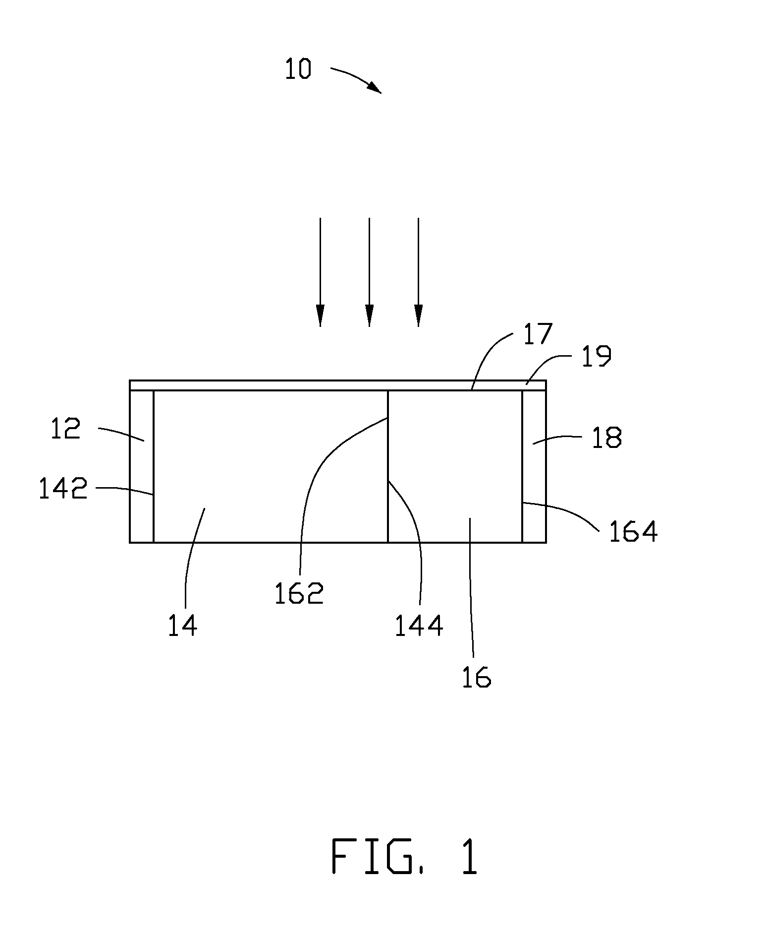
The present patent is about a solar cell system and a method for making it. The technical effect of the patent is to provide a solar cell with a high photoelectric conversion efficiency. The solar cell has a front electrode layer, a P-type silicon layer, an N-type silicon layer, and a second electrode layer arranged in series, side by side, in that order, cooperatively forming a planar structure with a photoreceptive surface for directly receiving incident light. The P-type silicon layer has a first surface and a second surface opposite to each other. The N-type silicon layer has a first surface and a second surface opposite to each other. The first side surface of the P-type silicon layer and the first side surface of the N-type silicon layer cooperatively form the photoreceptive surface. The technical effect of the patent is to provide a solar cell system with a high photoelectric conversion efficiency.

Problems solved by technology

However, a light absorbing efficiency of the P-N junction of the above solar cell is low, because partial photons in the incident light are absorbed by the front electrode and the N-type silicon layer.
Thus, carriers generated by exciting of photons in the P-N junction are relatively few, and a photoelectric conversion efficiency of the solar cell is relatively low.

Method used


Image

  • Solar cell, solar cell system, and method for making the same
  • Solar cell, solar cell system, and method for making the same
  • Solar cell, solar cell system, and method for making the same

Examples


Embodiment Construction

[0016]The disclosure is illustrated by way of example and not by way of limitation in the figures of the accompanying drawings in which like references indicate similar elements. It should be noted that references to “another,”“an,” or “one” embodiment in this disclosure are not necessarily to the same embodiment, and such references mean at least one.

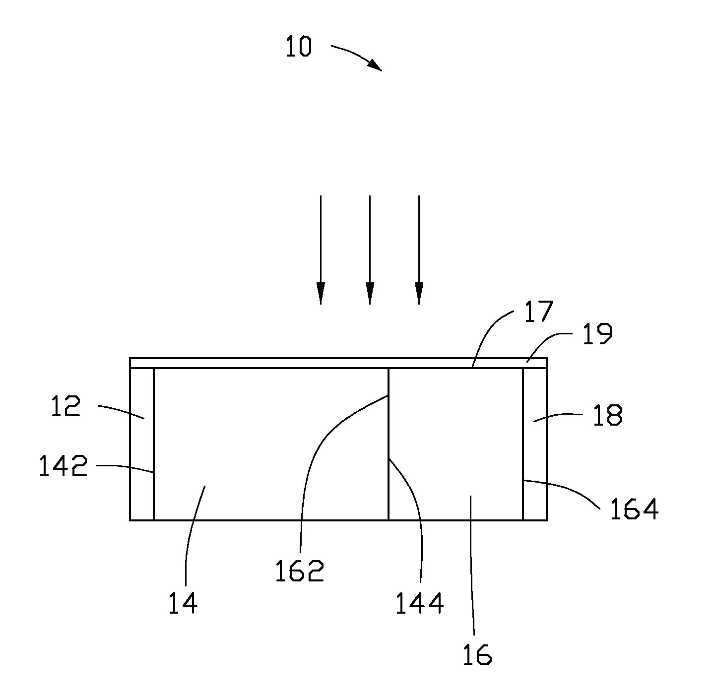
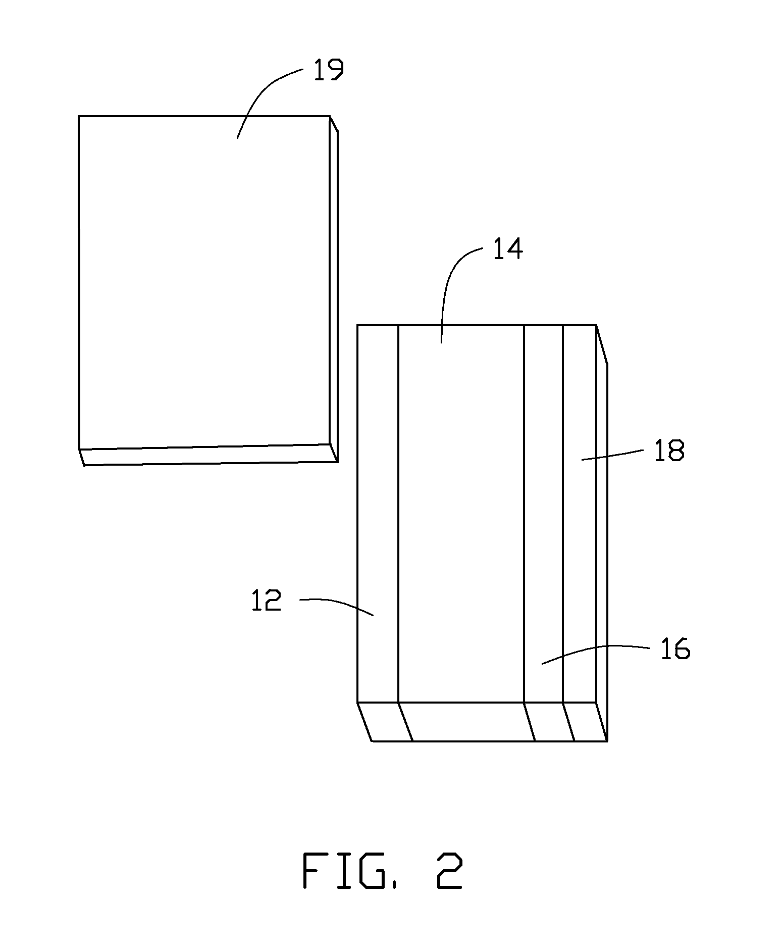
[0017]Referring to FIGS. 1 and 2, one embodiment of a solar cell 10 includes a first electrode layer 12, a P-type silicon layer 14, an N-type silicon layer 16, and a second electrode layer 18. The first electrode layer 12, the P-type silicon layer 14, the N-type silicon layer 16, and the second electrode layer 18 can be arranged in series, side by side, in that order, cooperatively forming a planar structure. The planar structure has a photoreceptive surface 17 across the planar structure of the first electrode layer 12, the P-type silicon layer 14, the N-type silicon layer 16, and the second electrode layer 18. The photoreceptive surf...


PUM


Abstract

A solar cell includes a first electrode layer, a P-type silicon layer, an N-type silicon layer, and a second electrode layer. The first electrode layer, the P-type silicon layer, the N-type silicon layer, and the second electrode layer are arranged in series side by side along a straight line and in contact with each other, thereby cooperatively forming a planar structure. The planar structure has a photoreceptive surface substantially parallel to the straight line and directly receives an incident light. A P-N junction is formed near an interface between the P-type silicon layer and the N-type silicon layer.

Description

CROSS-REFERENCE TO RELATED APPLICATIONS[0001]This application claims all benefits accruing under 35 U.S.C. §119 from China Patent Application No. 201010612753.X, filed on Dec. 29, 2010, in the China Intellectual Property Office, the contents of which are hereby incorporated by reference.BACKGROUND[0002]1. Technical Field[0003]The present disclosure relates to a solar cell, a solar cell system, and a method for making the same.[0004]2. Description of Related Art[0005]An operating principle of a solar cell is photoelectric effect of a semiconducting material. The solar cells can be roughly classified into silicon-based solar cells, gallium arsenide solar cells, and organic thin film solar cells.[0006]A silicon-based solar cell commonly includes a rear electrode, a P-type silicon layer, an N-type silicon layer, and a front electrode. The P-type silicon layer can be made of polycrystalline silicon or monocrystalline silicon and has a first surface and a flat second surface opposite to t...

Claims


Application Information

Patent Timeline
Patent Type & Authority Applications(United States)
IPC IPC(8): H01L31/042H01L31/0352H01L31/18
CPCH01L31/02168H01L31/022425H01L31/047Y02E10/547H01L31/068
Inventor FAN, SHOU-SHANJIN, YUAN-HAOLI, QUN-QING
Owner TSINGHUA UNIV
Learn More