
Light detecting apparatus and fluid measuring apparatus

a technology of light detecting apparatus and fluid measuring apparatus, which is applied in the direction of instruments, catheters, applications, etc., can solve the problem of hard to accurately detect and achieve the effect of accurately detecting a signal light componen

Active Publication Date: 2016-01-19
AIR WATER BIODESIGN INC
View PDF32 Cites 1 Cited by
  • Summary
  • Abstract
  • Description
  • Claims
  • Application Information

AI Technical Summary

Benefits of technology

The present invention aims to provide a light detection apparatus that can accurately detect a signal light component in light that is reflected, scattered, or the like by a test object. The invention also provides a fluid measuring apparatus that incorporates this light detection apparatus. This technology can improve the accuracy and reliability of detecting light from a tested object.

Problems solved by technology

If this type of light detecting apparatus is used as the light receiving unit of the laser Doppler blood flowmeter as described above, there is such a technical problem that it is hard to accurately detect a signal light component because intensity of the signal light component included in the light reflected or scattered by the living body (i.e. a Doppler-shifted modulation component) is less than that of a fixed light component included in the light reflected or scattered by the living body (i.e. a component which is not changed by the reflection or scattering by the living body).

Method used


Image

  • Light detecting apparatus and fluid measuring apparatus
  • Light detecting apparatus and fluid measuring apparatus
  • Light detecting apparatus and fluid measuring apparatus

Examples


examples

[0043]Hereinafter, examples of the present invention will be explained with reference to the drawings.

first example

[0044]A light detecting apparatus in a first example will be explained with reference to FIG. 1 to FIG. 3.

[0045]Firstly, a configuration of the light detecting apparatus in the first example will be explained with reference to FIG. 1 and FIG. 2.

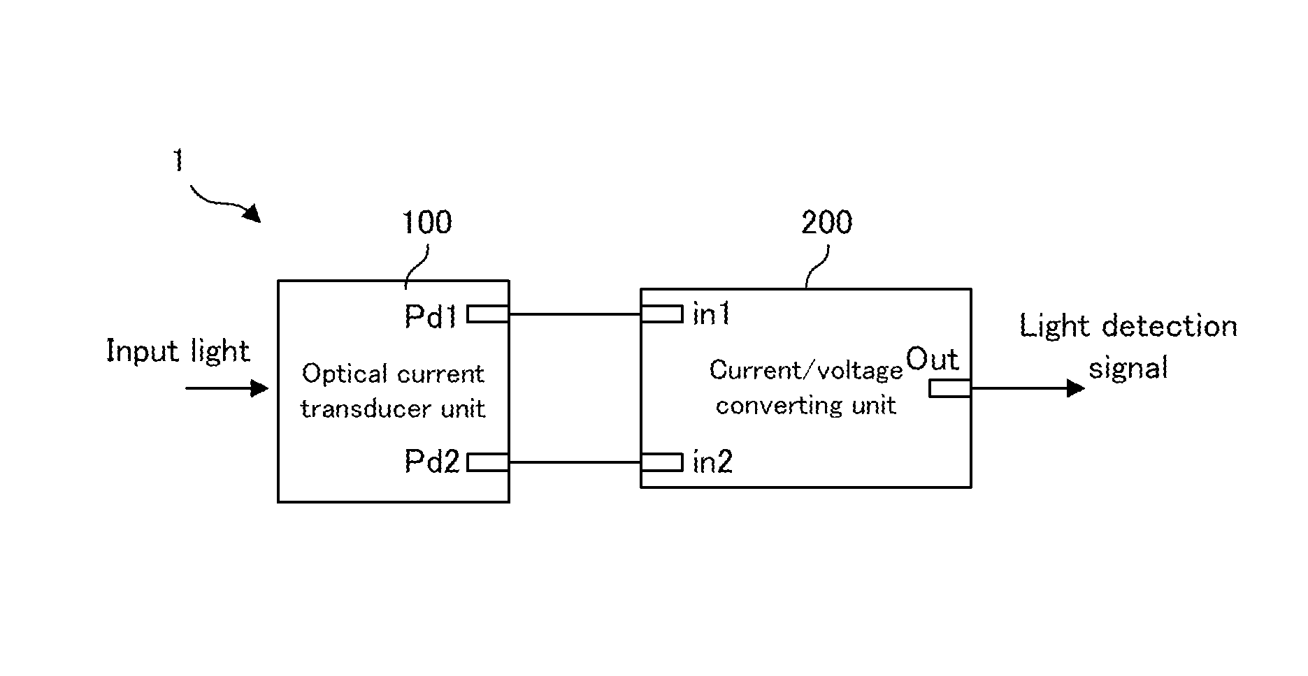
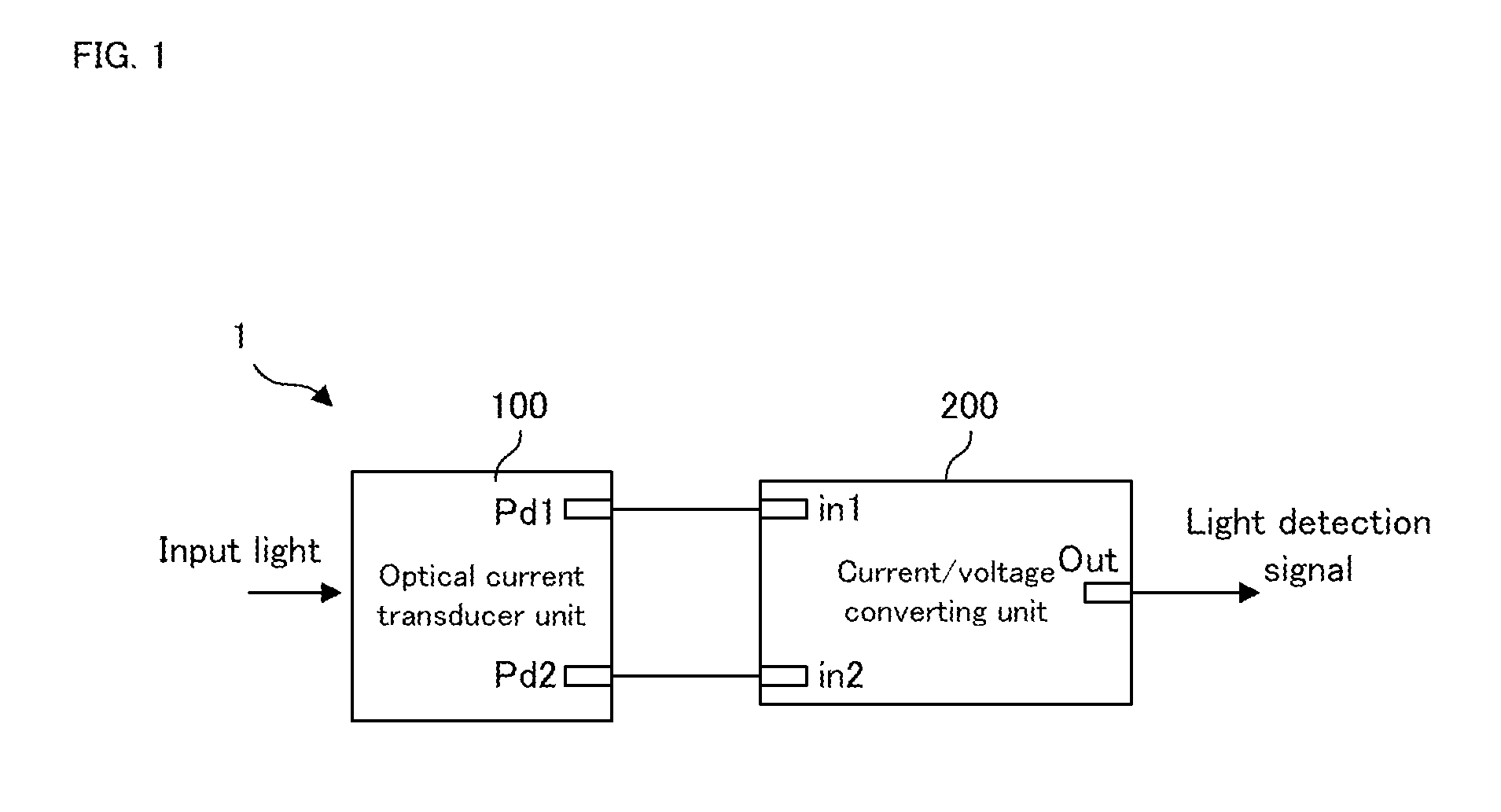
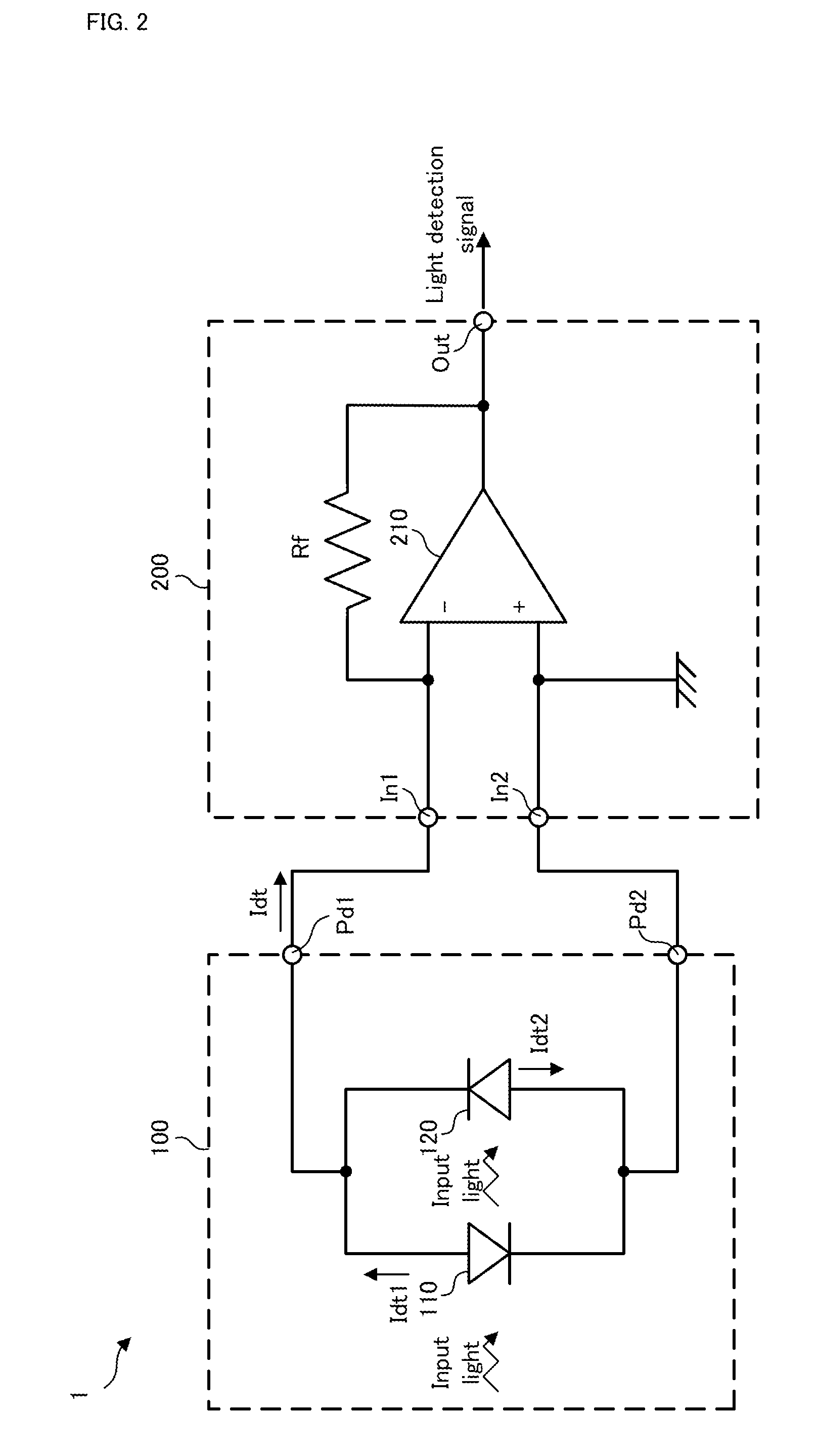
[0046]FIG. 1 is a block diagram conceptually showing an entire configuration of the light detecting apparatus in the first example. FIG. 2 is a block diagram showing a configuration of the light detecting apparatus in the first example.

[0047]In FIG. 1 and FIG. 2, a light detecting apparatus 1 in the first example is a light detecting apparatus for detecting a signal light component included in input light inputted from the exterior, which is provided with: an optical current transducer unit 100; and a current / voltage converting unit 200. The input light is, for example, light obtained by that laser light is reflected, scattered, or the like by a test object, a specimen, or an object to be examined (e.g. a human finger, etc.) and includes the ...

second example

[0066]A light detecting apparatus in a second example will be explained with reference to FIG. 4.

[0067]FIG. 4 is a block diagram showing a configuration of the light detecting apparatus in the second example. Incidentally, in FIG. 4, the same constituents as those in the first example shown in FIG. 2 will carry the same reference numerals, and the explanation thereof will be omitted, as occasion demands.

[0068]In FIG. 4, a light detecting apparatus 1b in the second example is different from the light detecting apparatus 1 in the first example described above in that there is provided an optical current transducer unit 100b instead of the optical current transducer unit 100 in the first example described above; however, in other points, the light detecting apparatus 1b is configured in substantially the same manner as the light detecting apparatus 1 in the first example described above.

[0069]In FIG. 4, the optical current transducer unit 100b has light receiving elements 110b and 120b...


PUM


Abstract

A light detecting apparatus includes: a first photoelectric conversion element unit (110) and a second photoelectric conversion element unit (120) each of which converts input light to an electric current and output it; an optical current transducer unit (100) for outputting, as a detected current, a differential current between an electric current outputted by the first photoelectric conversion element unit and an electric current outputted by the second photoelectric conversion element unit; and a first current / voltage converting unit (200) for amplifying the detected current outputted from the optical current transducer unit, converting it to a voltage signal, and outputting the voltage signal.

Description

TECHNICAL FIELD[0001]The present invention relates to, for example, a light detecting apparatus for detecting a signal light component included in light which is reflected, scattered, or the like by a test object, a specimen, or an object to be examined, and a fluid measuring apparatus, such as a laser Doppler blood flowmeter, provided with the light detecting apparatus.BACKGROUND ART[0002]As this type of light detecting apparatus, for example, there is an apparatus used as a light receiving unit for detecting light from a living body on a laser Doppler blood flowmeter (e.g. refer to patent documents 1 and 2). The laser Doppler blood flowmeter irradiates the living body with light such as laser light, and calculates blood flow velocity or the like of the living body from a change in wavelength due to a Doppler shift in the light reflection or scattering. The light detecting apparatus used as the light receiving unit of the laser Doppler blood flowmeter is typically provided with: a ...

Claims


Application Information

Patent Timeline
Patent Type & Authority Patents(United States)
IPC IPC(8): A61B8/00G01F1/66G01P5/26G01S17/58A61B5/026
CPCA61B5/0261G01F1/661G01F1/663G01F1/667G01P5/26G01S17/58
Inventor TATEISHI, KIYOSHIITO, ATSUYAKIMURA, YOSHINORI
Owner AIR WATER BIODESIGN INC
Learn More