
Apparatus and system for monitoring and managing traffic flow

a technology of traffic flow and apparatus, applied in the field of transportation, can solve the problems of low efficiency of traffic control equipment, high failure rate of loop detectors, limited capabilities, etc., and achieve the effect of providing extremely limited management and relatively expensive equipmen

Active Publication Date: 2015-12-29
TAYLOR DONALD WARREN
View PDF4 Cites 153 Cited by
  • Summary
  • Abstract
  • Description
  • Claims
  • Application Information

AI Technical Summary

Benefits of technology

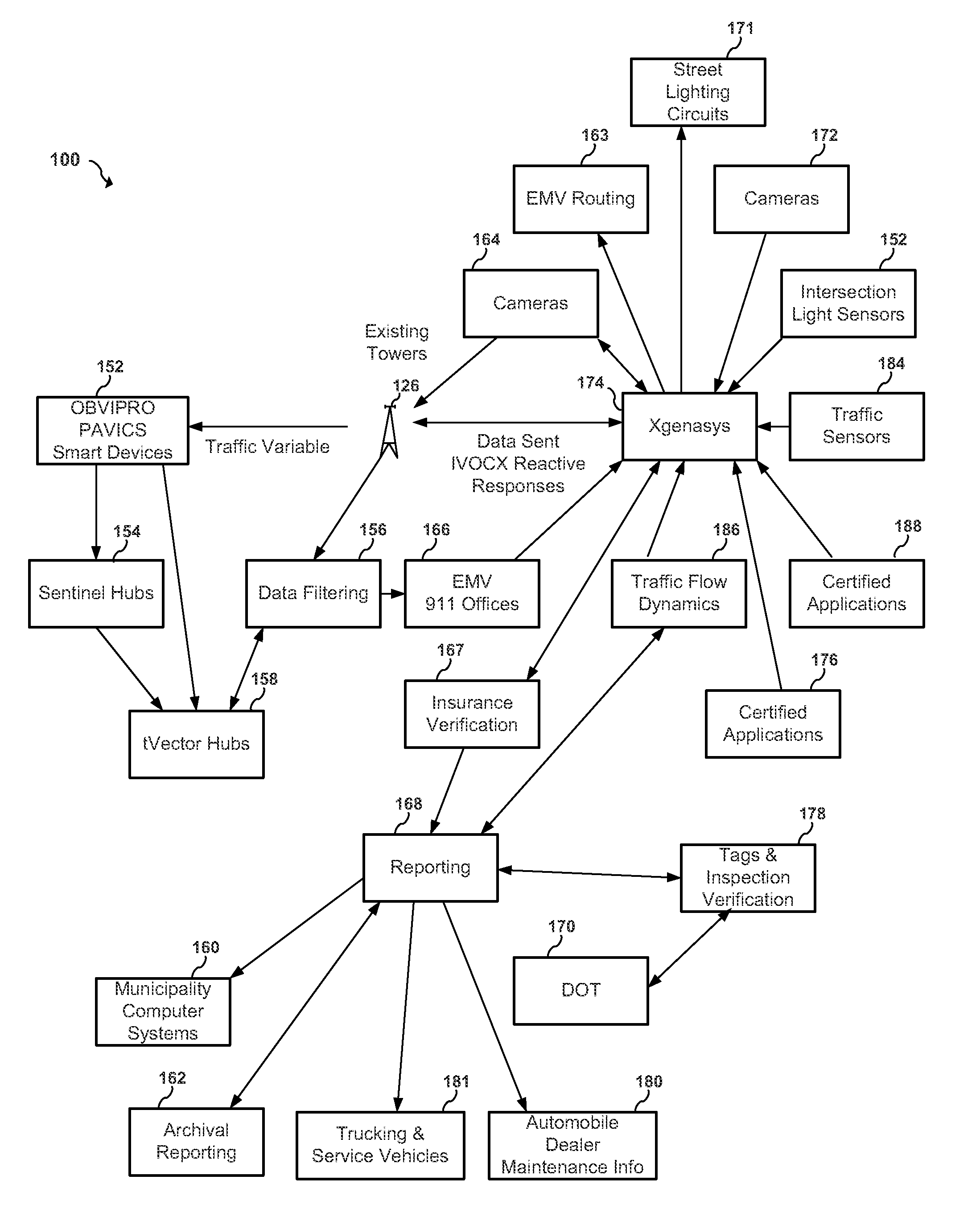
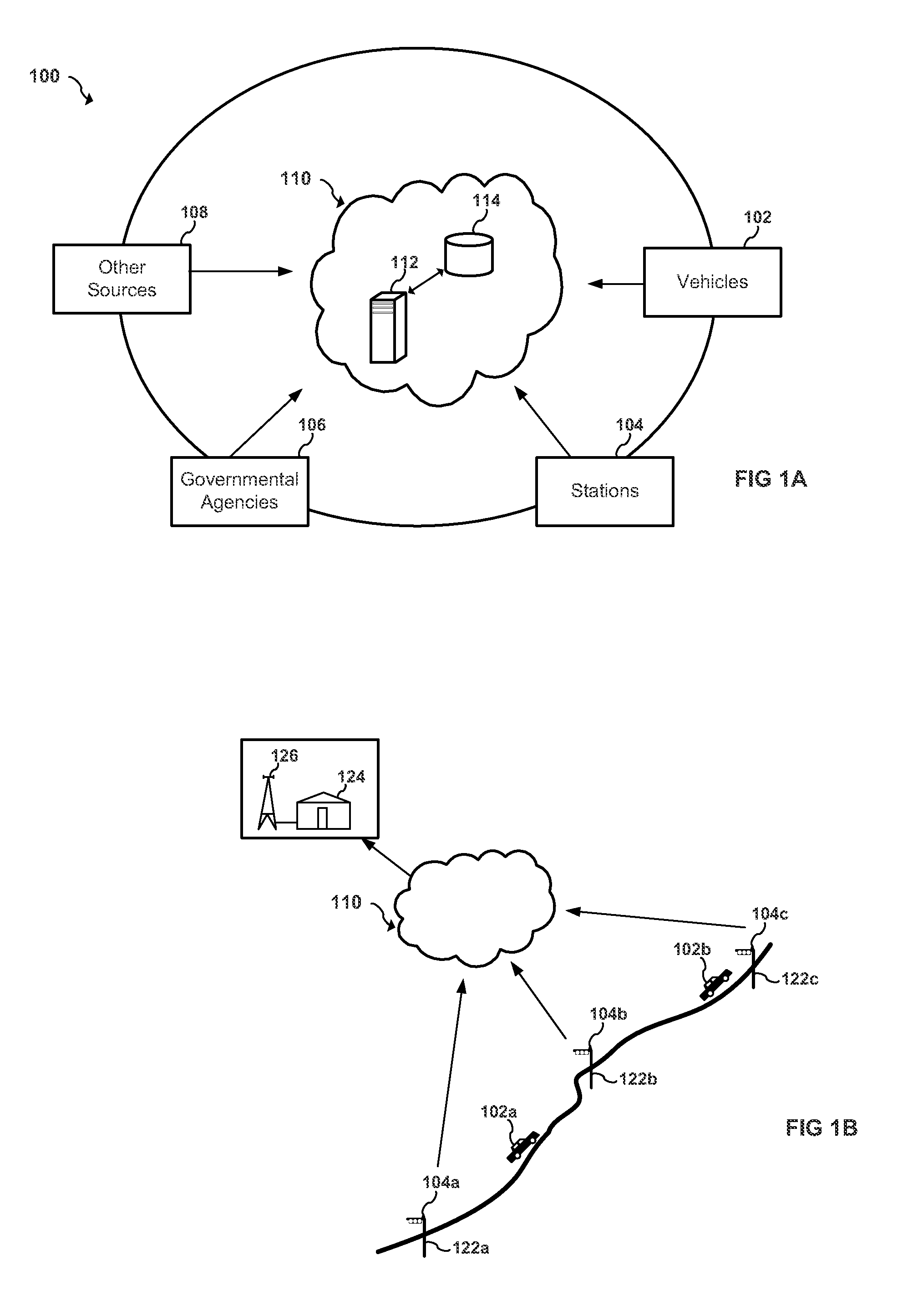
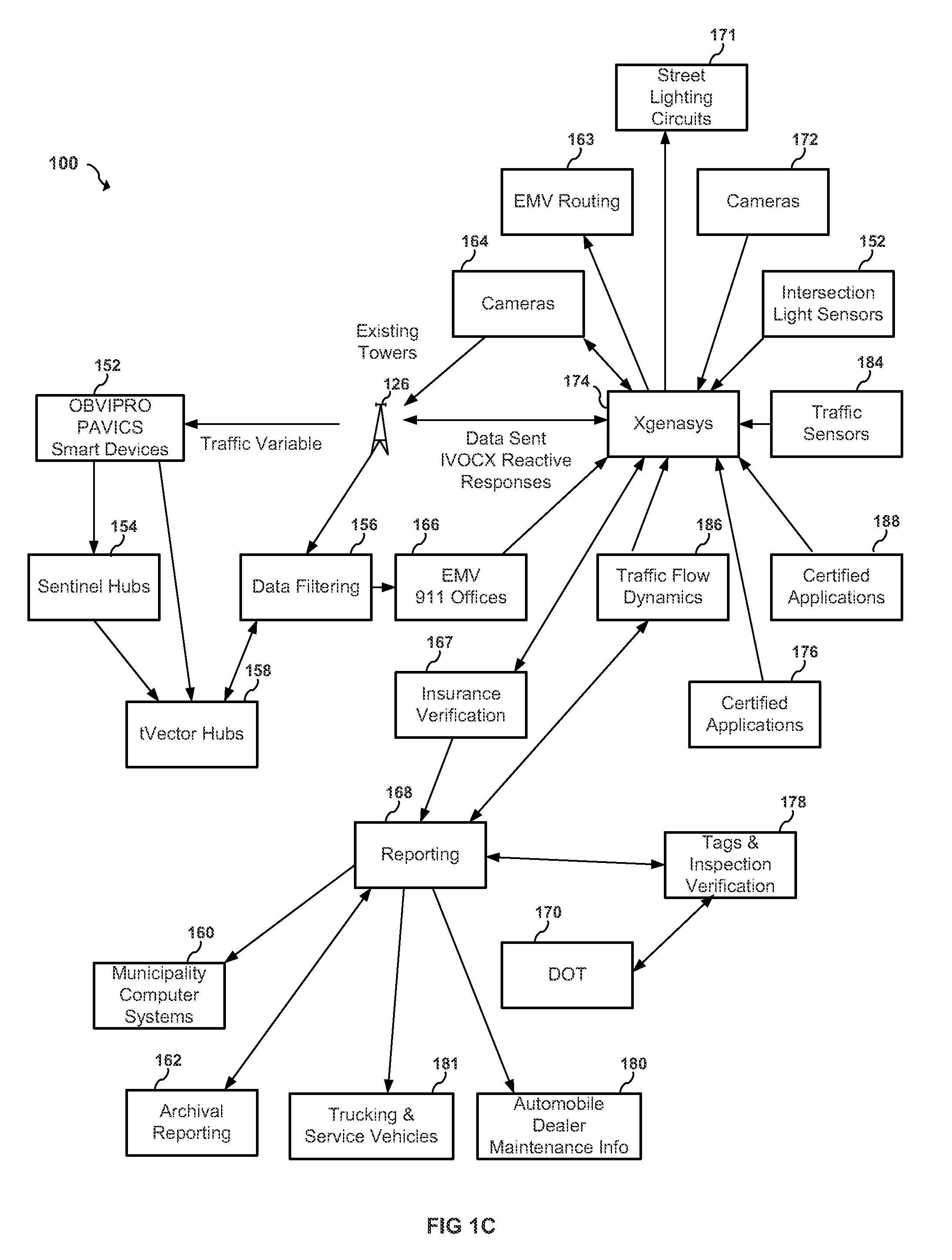
The present invention provides a system for monitoring and managing traffic flow by using multiple remote sensors and communication hubs along roadways. A central server receives traffic data from the sensors and updates it in a shared database. The server periodically calculates an optimal traffic flow for vehicles traveling along the roadways and transmits timing adjustments to traffic light intersections based on the optimal flow calculations. The system allows for real-time monitoring and management of traffic flow, improving efficiency and safety on the roadways.

Problems solved by technology

Existing systems generally depend on direct visual observations produced by infrared receivers for emergency vehicles that are not reactive enough if at all, video image vehicle detection system (VIVDS) that need to be humanly monitored and are inconsistent with detections due to having an engineer manually draw and adjust the detection zones repetitively, and loop detectors that are fairly expensive and have a high failure rate with limited capabilities.
Such techniques can only provide extremely limited management if any at all for vehicles and are too imprecise for more sophisticated management of traffic flow and there associated variables to maintain a safe network, energy consumption read outs, vehicular maintenance warnings, and the like, and are generally not automated.
Thus, there currently exist deficiencies in monitoring and managing traffic flow.

Method used


Image

  • Apparatus and system for monitoring and managing traffic flow
  • Apparatus and system for monitoring and managing traffic flow
  • Apparatus and system for monitoring and managing traffic flow

Examples


Embodiment Construction

[0012]Referring now to the drawings, wherein like reference numerals designate identical or corresponding parts throughout the several views, preferred embodiments of the present invention are described.

[0013]The present invention relates to an apparatus and system for monitoring and managing traffic flow in a road network in an area served by one or more receiving stations receiving geographic positional and other data from one or more vehicles. According to one embodiment, the geographic positional data from one or more vehicles may utilize devices having the Autovecth Integrated Chip Set (RFIDGPS), also referred to “AVICS” devices. According to other embodiments, the geographic positional data is received from commercially available consumer devices, such as without limitation, mobile phones, smart phones, PDAs, GPS receivers and the like. The geographic positional data may include information received without limitation from satellites and the like. The geographic positional dat...


PUM


Abstract

An apparatus and system for monitoring and managing traffic flow. The system includes a plurality of remote sensor devices arranged in a plurality of vehicles, a plurality of remote communication hub devices operatively arranged along one or more roadways and in communication with the plurality of remote sensor devices, a central server, a network interface in communication with the central server and the plurality of remote communication hub devices over a network, and a shared database in communication with the central server. The central server is configured to receive traffic data from the plurality of remote sensor devices over the network, update traffic data in the shared database, periodically calculate an optimal traffic flow for one or more of vehicles traveling along the one or more roadways based on the updated traffic data, and transmit timing adjustments over the network to one or more traffic light intersections based on the optimal traffic flow calculations. The network interface is configured to send and receive traffic data. The traffic data includes vehicle location information and network traffic congestion information.

Description

CROSS REFERENCE TO RELATED APPLICATIONS[0001]The present application is a continuation-in-part of and claims priority to U.S. patent application Ser. No. 13 / 815,807, entitled “Apparatus and System for Monitoring and Managing Traffic Flow,” filed in the U.S. Patent and Trademark Office on Mar. 15, 2013, having at least one common inventor as the present document and hereby incorporated by reference.BACKGROUND OF THE INVENTION[0002]1. Field of the Invention[0003]The present invention is generally related to transportation, and more particularly to an apparatus and system for monitoring and managing traffic flow.[0004]2. Discussion of the Background[0005]With ever increasing road traffic levels there is a particular need for the monitoring and management of traffic congestion, fuel consumption, environmental concerns from C02, safety related concerns, traffic flow and idle time. Existing systems generally depend on direct visual observations produced by infrared receivers for emergency...

Claims


Application Information

Patent Timeline
Patent Type & Authority Patents(United States)
IPC IPC(8): G08G1/08G08G1/01
CPCG08G1/08G08G1/0145G08G1/0116G08G1/0112
Inventor TAYLOR, DONALD WARREN
Owner TAYLOR DONALD WARREN
Learn More