
Power plant

a power plant and cogeneration technology, applied in the direction of engine starters, engine/propulsion engine ignition, engine/propulsion engine damage, etc., can solve the problems of increased life expenditure of hrsg, thermal stress on hrsg components, damage to hrsg,

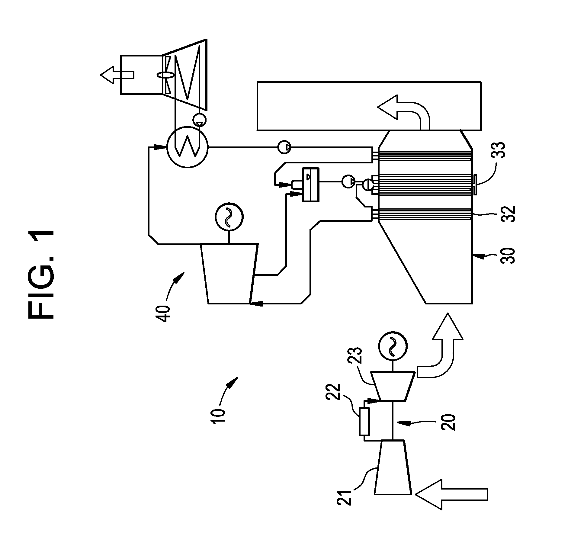
Active Publication Date: 2015-12-29
GENERAL ELECTRIC CO
View PDF107 Cites 14 Cited by
  • Summary
  • Abstract
  • Description
  • Claims
  • Application Information

AI Technical Summary

Benefits of technology

[0007]According to another aspect of the invention, a method of operating a power plant is provided and includes controlling one or more detectors disposed in a heat recovery steam generator (HRSG) to rotate, pivot or move in one or more of height, width and depth directions, processing output of the one or more detectors to generate images, analyzing the images to identify hot spots in the HRSG and, once one or more hot spots are identified, maneuvering and controlling an eductor assembly in the HRSG to reduce the hot spots.
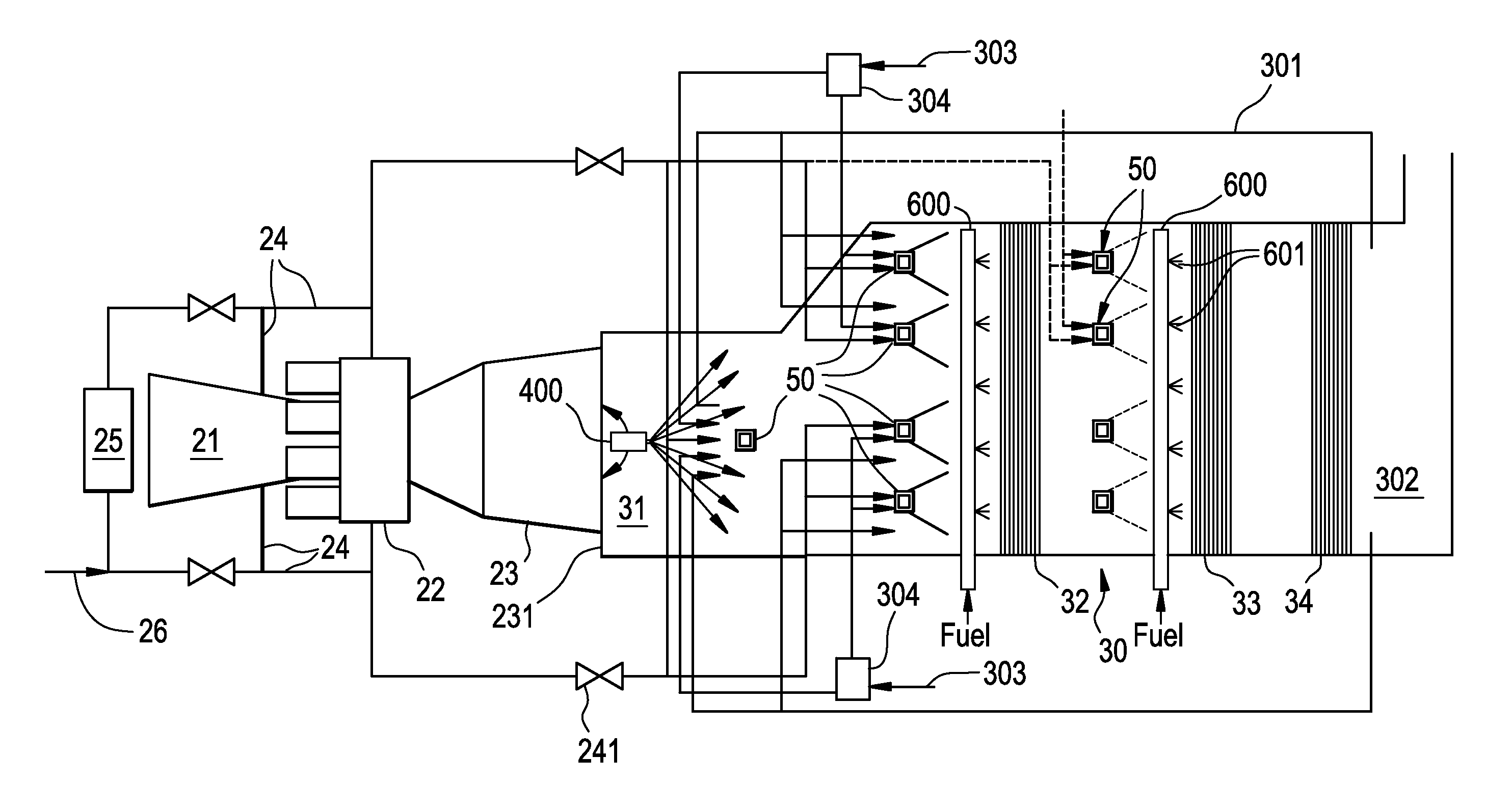
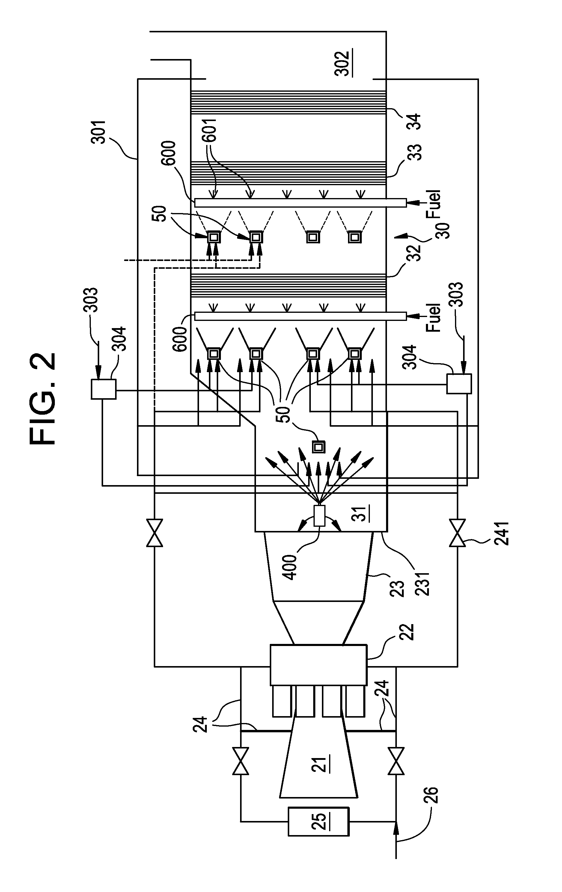
[0008]According to yet another aspect of the invention, a power plant is provided and includes a gas turbine engine to generate power, a heat recovery steam generator (HRSG) to produce steam from high energy fluids produced from the generation of power in the gas turbine engine, a steam turbine engine to generate power from the steam produced in the HRSG, an eductor assembly by which a mixture of compressor discharge air and entrained fluids is injectable into the HRSG and a duct burner disposed within the HRSG, the duct burner being configured to fire in a presence of the mixture to increase steam production in the HRSG.

Problems solved by technology

During startup operations of the combined cycle plant, the gas turbine(s) feed exhaust energy to the HRSG to produce steam but the rate of change of gas turbine exhaust energy to the HRSG causes thermal stresses to the HRSG components.
These stresses can lead to damage that impacts the life of the HRSG.
Therefore, a primary limitation in fast starting combined cycle power plants is the additional life expenditure per start that the HRSG experiences.
In fact, in spite of the financial benefits of starting up power plants faster, the impact on HRSG life expenditure makes customers wary of technologies that help combined cycle plants startup faster.

Method used


Image

  • Power plant
  • Power plant
  • Power plant

Examples


Embodiment Construction

[0018]Aspects of the present invention are directed to comprehensive strategies to manage impact of gas turbine exhaust energy during combined cycle startup operation and / or part load operation. The strategies include but are not limited to management of thermal stresses in critical areas of a heat recovery steam generator (HRSG) during startup and reductions in gas turbine exhaust energy during startup and / or part load operations.

[0019]Startup operations of a combined cycle power plant or a cogeneration power plant (hereinafter referred to as a “power plant”) include gas turbine engine startup whereby a combustor lights-off and a flame is established in the combustor. Hot exhaust gases are produced and quickly propagate downstream and can impinge on HRSG components that are located aft of the gas turbine engine exit flange. This can cause the HRSG components to undergo a rapid change in temperature from less than 0° Fahrenheit to above 1200° Fahrenheit in under 10 seconds as the fl...


PUM


Abstract

A power plant is provided and includes a gas turbine engine to generate power, a heat recovery steam generator (HRSG) to produce steam from high energy fluids produced from the generation of power in the gas turbine engine, a steam turbine engine to generate additional power from the steam produced in the HRSG and a thermal load reduction system to reduce thermal loading of components of the HRSG and / or the steam turbine engine during at least startup and / or part load operations, which includes an eductor by which a mixture of compressor discharge air and entrained ambient air is injectable into the HRSG and / or an attemperator to cool superheated steam to be transmitted to the steam turbine engine and a detector disposed within the HRSG to facilitate identification of hot spots therein.

Description

CROSS-REFERENCE TO RELATED APPLICATIONS[0001]This application is a continuation-in-part of co-pending application Ser. No. 13 / 086,119, entitled “COMBINED CYCLE POWER PLANT,” which was filed on Apr. 13, 2011, the entire contents of which are incorporated herein by reference.BACKGROUND OF THE INVENTION[0002]The subject matter disclosed herein relates to a power plant and, more particularly, to a combined cycle power plant or a cogeneration power plant.[0003]A combined cycle power plant consists of several pieces of major equipment. These include the gas turbine(s), a steam turbine and heat recovery steam generators (HRSG). The gas turbine produces power and exhaust energy. The gas turbine exhaust energy is captured by the HRSG and is used to convert water to steam, which is then expanded in the steam turbine to produce additional power.[0004]During startup operations of the combined cycle plant, the gas turbine(s) feed exhaust energy to the HRSG to produce steam but the rate of change...

Claims


Application Information

Patent Timeline
Patent Type & Authority Patents(United States)
IPC IPC(8): F02C6/00F02C6/08F02C6/18F02C7/18F02C7/26F01K23/10F22G3/00
CPCF02C6/08F01K23/101F02C6/18F02C7/18F02C7/26Y02E20/16F05D2260/80F05D2260/941F22G3/008Y02E20/14
Inventor CHILLAR, RAHUL JAIKARANCHRISWINDARTO, WULANG EDWIENEKANAYAKE, SANJIMESTRONI, JULIO ENRIQUENENMENI, VIJAY RAGHAVENDRANPANDEY, ACHALESH KUMARROGERS, DAVID LEESALTER, MORGAN CARTHLEDGESRIVASTAVA, AJIT
Owner GENERAL ELECTRIC CO
Learn More