
Quick assembly and disassembly mechanism

a technology of assembly and disassembly mechanism, which is applied in the direction of screws, threaded fasteners, bolts, etc., can solve the problems of difficult operation, time and energy, and difficulty in locking or unlocking nuts, so as to achieve convenient and quick

Active Publication Date: 2015-12-29
XIAMEN LOTA INT CO LTD
View PDF8 Cites 10 Cited by
  • Summary
  • Abstract
  • Description
  • Claims
  • Application Information

AI Technical Summary

Benefits of technology

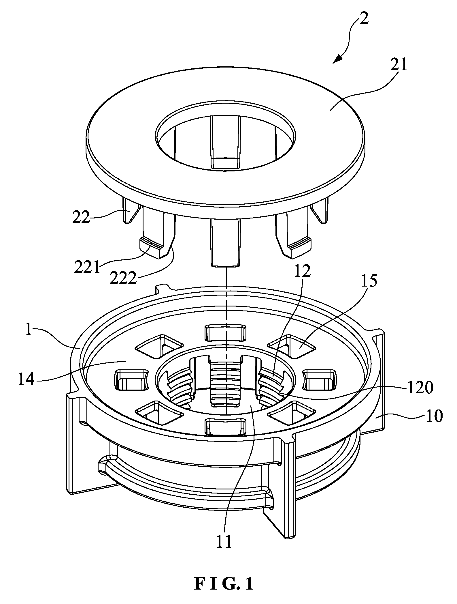
The present invention provides a mechanism for quickly and easily assembling and disassembling a faucet and its related parts. This mechanism includes a nut seat with at least two lock blocks that can be moved freely on a bolt. The nut seat collaborates with a slide block that is connected to the nut seat. The slide block has an inclined push surface that pushes the inclined guide surface of the lock blocks, allowing the faucet to be mounted and dismounted quickly. This mechanism makes the assembly and disassembly process of the faucet and its related parts more convenient and efficient.

Problems solved by technology

Thus, to lock or unlock the nut takes time and energy.
It also takes time and energy.
Because the space under the counter top is narrow, it is difficult to operate.
The faucet cannot be dismounted quickly.

Method used


Image

  • Quick assembly and disassembly mechanism
  • Quick assembly and disassembly mechanism
  • Quick assembly and disassembly mechanism

Examples


first embodiment

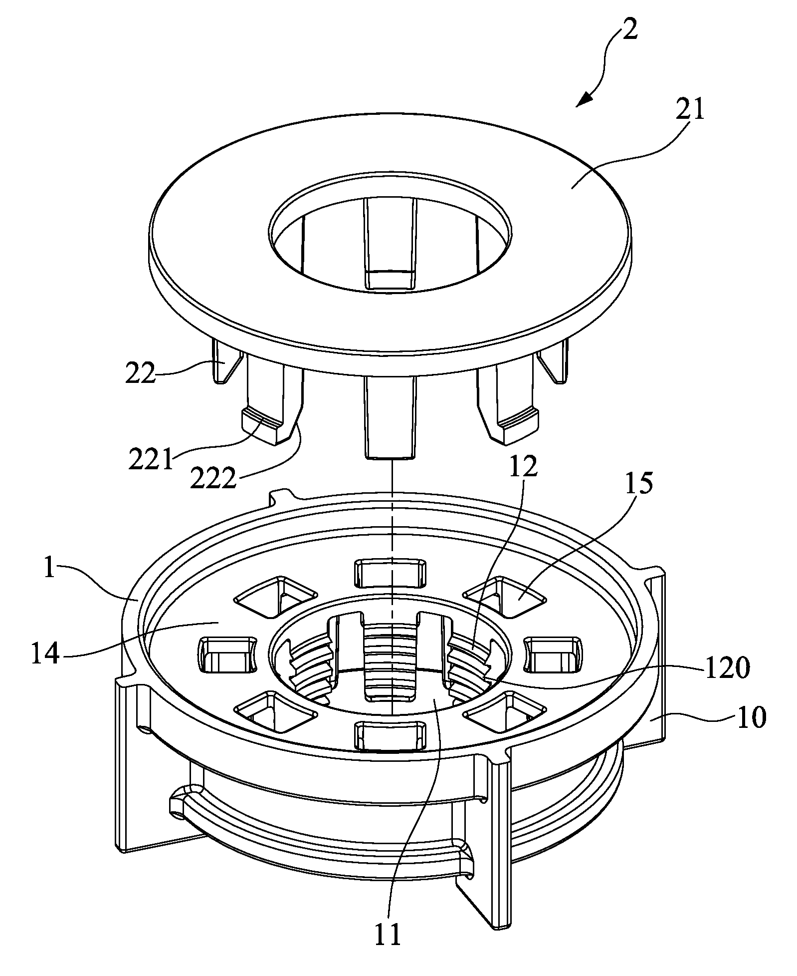
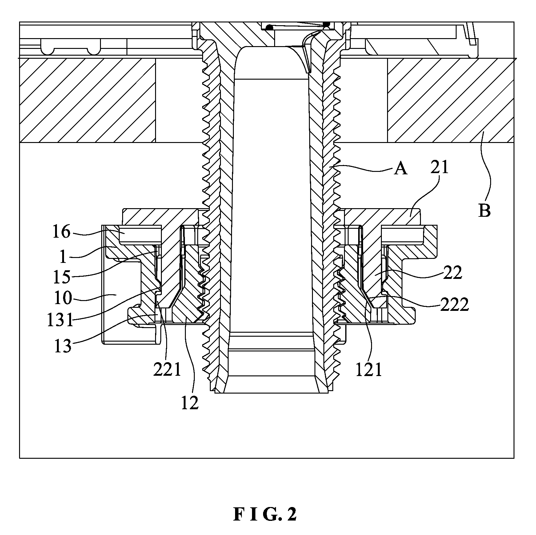
[0025]FIG. 1 to FIG. 3 shows the quick assembly and disassembly the present invention. Wherein, the lower end of the insertion room 11 of the nut seat 1 is provided with a plurality spaced cantilever lock blocks 12 which are disposed vertically around the circumference of the insertion room 11 from top to bottom. Each lock block 12 has a connecting surface 14 at an upper end thereof. The connecting surface 14 has an insertion hole 15 for insertion of each claw 22 of the slide block 2 to be inserted into the insertion seat 13. The connecting surface 14 is formed with a depression seat 16 relative to the top end of the nut seat 1. The height of the depression seat 16 is slightly larger than the thickness of an annular surface 21 of the slide block 2, such that the upper surface of the slide block 2 and the top surface of the nut seat 1 are on the same plane to cooperate with the counter top B conveniently. The outer wall of the lower portion of each lock block 12 is formed with an inc...

second embodiment

[0031]FIG. 4 to FIG. 6 shows the quick assembly and disassembly the present invention. Wherein, the insertion room 11 of the nut seat 1 is provided with a plurality spaced cantilever lock blocks 12 which are disposed upwardly and vertically around the circumference of the insertion room 11. The outer wall of the upper portion of each lock block 12 is formed with an inclined guide surface 121 which is expanded outwardly from top to bottom. The inner wall close to the middle portion of the insertion seat 13 of the nut seat 1 is provided with a plurality of ledges 131 to prevent disengagement.

[0032]In this embodiment, the slide block 2 is an insertion ring. The outer wall of the slide block 2 is formed with recesses 23 corresponding to the ledges 131. The slide block 2 has engaging legs 24 at the lower ends of the recesses 23 to cooperate with the ledges 131. The inner wall close to the upper portion of the slide block 2 is formed with an inclined push surface 25 which is expanded outw...


PUM


Abstract

A quick assembly and disassembly mechanism includes a nut seat and a slide block which is movably coupled to the nut seat. The nut seat includes at least two cantilever lock blocks therein. The inner wall of each lock block has threads thereon. The inner diameter encircled by the lock blocks matches with a bolt of a faucet. In normal state, the nut seat can be moved freely on the bolt. When the nut seat is moved to a counter top to compress the slide block, the slide block will push the lock blocks to mesh with the bolt tightly, so that the faucet can be mounted and dismounted quickly.

Description

BACKGROUND OF THE INVENTION[0001]1. Field of the Invention[0002]The present invention relates to a quick assembly and disassembly mechanism, and more particularly to a quick assembly and disassembly mechanism for the faucet and its parts of a bathroom sink and a kitchen sink.[0003]2. Description of the Prior Art[0004]When a faucet is installed at one side of a sink, a nut is used to mesh with the bolt at the lower end of the faucet so that the faucet can be installed on the counter top. The faucet of the kitchen and the bathroom is installed close to the wall. Subject to the shape of the kitchen sink and the bathroom sink, the space under the counter top to lock the faucet is very small. According to the traditional operation to lock the nut on the bolt, the nut must be rotated from the lower end of the bolt. The length of the bolt depends on the thickness of the counter top, namely, it decides the route of the nut to be locked. Thus, to lock or unlock the nut takes time and energy....

Claims


Application Information

Patent Timeline
Patent Type & Authority Patents(United States)
IPC IPC(8): E03C1/042F16B39/36F16B39/06E03C1/04F16B29/00
CPCE03C1/04E03C1/0401Y10T137/598F16B29/00
Inventor YE, LIMINGBAI, SHUANGLINZHOU, JIANPING
Owner XIAMEN LOTA INT CO LTD
Learn More