
Toric lens with decreased sensitivity to cylinder power and rotation and method of using the same

a toric lens and cylinder power technology, applied in the field of vision correction, can solve the problems of blurred vision, astigmatic condition may worsen, astigmatic correction is an optical defect, etc., and achieve the effects of reducing the sensitivity of the toric intraocular element, reducing the sensitivity of astigmatic correction, and reducing the sensitivity of alignment errors

Active Publication Date: 2015-12-22
AMO GRONINGEN
View PDF287 Cites 7 Cited by
  • Summary
  • Abstract
  • Description
  • Claims
  • Application Information

AI Technical Summary

Benefits of technology

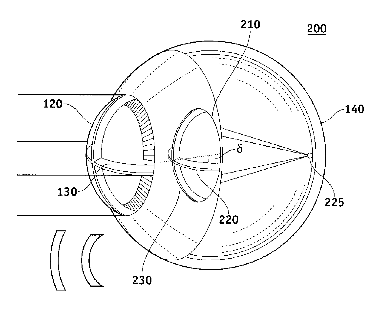
The present invention is about a new type of lens that can correct astigmatism. It includes a toric element and a depth of focus extender that helps to reduce sensitivity to errors in cylinder power selection and lens rotational alignment. This makes it easier to choose the correct lens and reduces the risk of complications during surgery. The technical effect of this invention is to provide a more reliable and effective method for correcting astigmatism.

Problems solved by technology

If the insertion angle is not correct and / or maintained, the astigmatism will not be fully corrected, and in fact the astigmatic condition may worsen.
Generally, astigmatism is an optical defect in which vision is blurred due to the ocular inability to focus a point object into a sharply focused image on the retina.
However, any misalignment of the compensating optic, and / or improper selection of the corrective lens, may cause residual cylinder, or further astigmatism, and potentially induce other aberrations.
Thus, two specific issues arise from using a lens, such as an IOL, to correct astigmatism.
First, toric ophthalmic lenses are sensitive to cylinder orientation misalignment relative to that to be corrected, such as wherein the axis of the toric lens in the eye and the lens for correction are not accurately aligned.
Second, the cylinder power of the eye or cornea may not sufficiently match the power of the toric IOL.
This may be due to measurement errors, unintended changes of cylinder power and / or axis during or after surgery, or because current toric lenses are offered only in a number of discrete cylinder increments.

Method used


Image

  • Toric lens with decreased sensitivity to cylinder power and rotation and method of using the same
  • Toric lens with decreased sensitivity to cylinder power and rotation and method of using the same
  • Toric lens with decreased sensitivity to cylinder power and rotation and method of using the same

Examples


Embodiment Construction

[0032]It is to be understood that the figures and descriptions of the present invention have been simplified to illustrate elements that are relevant for a clear understanding of the present invention, while eliminating, for the purpose of clarity, many other elements found in typical lenses, lens systems and methods. Those of ordinary skill in the pertinent arts may recognize that other elements and / or steps are desirable and / or required in implementing the present invention. However, because such elements and steps are well known in the art, and because they do not facilitate a better understanding of the present invention, a discussion of such elements and steps is not provided herein. The disclosure herein is directed to all such variations and modifications to such elements and methods known to those skilled in the pertinent arts.

[0033]Embodiments described herein provide a corrective lens, such as a toric lens, e.g. a toric IOL, toric contact lens, and / or toric inlay / onlay, ha...


PUM


Abstract

A method, system and apparatus for vision correction are disclosed. The method, system and apparatus include a toric intraocular element for correcting astigmatism and having a cylinder power, and a depth of focus extender coupled to the toric intraocular element, the depth of focus extender extending a depth of focus. The extended depth of focus may reduce sensitivity of the toric intraocular element to at least one of rotation and selected cylinder power.

Description

CROSS-REFERENCE OF RELATED APPLICATIONS[0001]This application claims priority to and is a continuation-in-part application of U.S. application Ser. No. 12 / 120,201, filed on Apr. 13, 2008, which is hereby incorporated by reference as if set forth herein in its entirety. This application also claims priority to and is a continuation-in-part application of U.S. application Ser. No. 12 / 197,249, filed on Aug. 23, 2008, which claims priority to U.S. Provisional Application No. 60 / 968,250, filed on Aug. 27, 2007, each of which is hereby incorporated by reference as if set forth herein in its entirety.FIELD OF THE INVENTION[0002]The present invention is related to vision correction, and, more particularly, to vision correction using a toric lens with decreased sensitivity to cylinder power and rotation.BACKGROUND OF THE INVENTION[0003]Surgery on the human eye has become commonplace in recent years. Many patients pursue eye surgery as an elective procedure, such as to avoid the use of contac...

Claims


Application Information

Patent Timeline
Patent Type & Authority Patents(United States)
IPC IPC(8): A61F2/16G02B3/06G02B27/00G02C7/02G02C7/04
CPCA61F2/1654A61F2/1645G02B3/06G02B27/0075G02C7/041G02C7/02G02C2202/20A61F2002/1699G02C2202/02A61B3/0025A61F9/013G02C7/027G02C7/06G02C2202/06
Inventor BOGAERT, THEOPHILUSWEEBER, HENDRIK A.ZHAO, HUAWEI
Owner AMO GRONINGEN
Learn More